


Factory Service Manual For Bomag Road Finisher. Manual Contains Illustrations, Instructions, Diagrams For Step By Step Remove And Install, Assembly And Disassembly, Service, Inspection, Repair, Troubleshooting, Tune-Ups.
Format: PDF
Language: ENG
Pages: 954
Number: 00891773 (february 2013)
Bookmarks: Yes
Searchable: Yes
Wiring Diagrams: Yes
Hydraulic Diagrams: Yes
Model
Bomag Road Finisher
BF800C
S/N 821 837 17 1001 ….
S/N 821 837 71 1001 ….
S/N 821 837 19 1001 ….
S/N 821 837 66 1001 ….
S/N 861 893 50 1001 ….
S/N 861 893 60 1001 ….
Contents
-GENERAL
Introduction
Safety Regulations
General Repair Instructions
Tightening Torques
-TECHNICAL DATA
Technical Data
-MAINTENANCE
General Notes On Maintenance
Fuels And Lubricants
Table Of Fuels And Lubricants
Running-In Instructions
Maintenance Table
-E-PLAN WIRING DIAGRAMS
Understanding E-Plan Circuit Diagrams
Circuit Symbols In E-Plan
Identification Of Switch Blocks In The Wiring Diagram
Designation Of Components In The Wiring Diagram
Terminal Designations In Wiring Diagram
-ENGINE
Diesel Engine
Engine Description TCD 2012
Lubrication Oil Circuit TCD 2012/2013
Coolant Circuit TCD 2012 / 2013
Fuel System TCD 2012 / 2013
Deutz Common Rail (DCR) Injection System For TCD 2012 / 2013
Exhaust Gas Recirculation TCD 2012 / 2013
Wastegate – Charge Pressure Controller On TCD-Engines
Engine Problems
Checking The Engine Oil Level
Changing Engine Oil And Oil Filter Cartridge
Replacing The Fuel Pre-Filter Cartridge, Bleed The Fuel System
Replace The Fuel Filter
Check, Clean The Water Separator
Check The Coolant Level
Replace The Coolant
Checking The Thermostat In Disassembled State
Air Filter Maintenance
Clean The Cooling Fins On Engine And Hydraulic Oil Cooler
Intercooler, Drain Off Oil And Condensation Water
Adjust The Valve Clearance
Checking The Ribbed V-Belt, Replacing If Necessary
Replace The Crank Case Ventilation Valve
Engine Conservation
Special Tools, Deutz Engine (TCD 2012 2V)
-ENGINE ELECTRICS
EMR3 System Components
Deutz EMR3 – Engine Connections
Pin Assignment Of Engine Control Edc16 / Emr3
Rotary Speed Sensor For Camshaft
Crankshaft Speed Sensor
Rail Pressure Sensor
Fuel Pressure Sensor
Fuel Control Unit
Injector
Oil Pressure Sensor
Sensor For Charge Air Temperature And Charge Air Pressure
EMR Coolant Temperature Sensor
Glow Plugs
Sensor, Water In Fuel
Air Filter Vacuum Switch
Float Switch, Coolant Tank
Charge Control Light, Engine Rpm-Meter
Diagnose With Serdia
Diagnose With Can-Bus
Diagnostics Interface
Emr3 List Of Fault Codes
Generator
Replacing The Voltage Regulator
Electric Starter
-ELECTRICS
Service The Battery, Check The Main Battery Switch
Starting The Engine With Jump Leads
Starting With Jump Wires
Fuses
Fuse Assignment
Component Overview – Electrics
Overview Of Wiring Looms
Control Elements
View Of Control Panel
Instrument Cluster
Data Collector
View Of External Operator Stations
View Of External Operator Stations
View Of Screed Control Panel
View Of Electric Heating Control Panel
Functional Block Diagram Overview Of Functions, Complete
Block Diagram Components On CAN
Block Diagram CAN With Control Elements
Block Diagram Of Travel Circuit
Block Diagram Material Feed
Block Diagram Screed
Block Diagram Screed Heating
Functional Block Diagram Monitoring Functions
Block Diagram Emergency Stop Functions
Electronic Control Units
Checking The Voltage Supply For The Control Unit
Diagnostics Concept
-ERROR CODES — GENERAL INFORMATION
Error Codes – BF800 – General Information
-INPUT CODES
Input Codes
-REPLACEMENT OF COMPONENTS
How To Proceed When Replacing Components
-MATERIAL HOPPER, DESCRIPTION
Material Hopper And Transport
-VIBRATING SCREED, DESCRIPTION
Screed
-BASIC SETTINGS ON THE SCREED
Notes On The Screed Adjustment (Type S500 & S600)
Bringing The Straight Crossfalls To Zero Position
Aligning Basic Screed And Mobile Sections
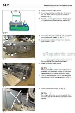
-ASSEMBLING THE SCREED EXTENSIONS
Notes On Assembling Screed Extensions
Assembling The Screed Extensions
-ELECTRIC SCREED HEATING, REPAIR
Electric Screed Heating
Electric Screed Heating – Commissioning
Faults In The Electric Heating
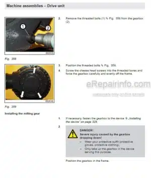
-TRAVEL DRIVE, DESCRIPTION
Travel System
-HYDRAULICS
Hydraulic Circuit
Component Overview — Hydraulics
Description Of Travel Pump
View Of The Machine
Pumps For: Scraper Belt, Augers, Vibration & Tampers
View Of The Machine
Description Of Fan Pump
View Of The Machine
Description Of Charge Pumps
Check The Hydraulic Oil Level
Change Hydraulic Oil And Hydraulic Oil Filter
-HYDRAULICS – TRAVEL CIRCUIT
Description Of Driving
Description Of Brake Circuit
-HYDRAULICS – MATERIAL TRANSPORT
Description Of Scraper Belts
Description Of Augers
Description Tamping
Description Vibration
-HYDRAULICS – SERVICE
Description Of Fan Circuit
Description Of Service (A)
Description Of Service (B)
Description Of Load Control System (LCS)
-TESTS AND ADJUSTMENTS
Special Tools, Tests And Adjustments
Checking And Adjusting The Vibration
Checking/Adjusting Tamping
Checking/Adjusting The Scraper Belts
Checking/Adjusting The Augers
Checking & Adjusting The Service Pump/Cylinder Functions
Checking & Adjusting The Time For Screed Levelling
Checking/Adjusting The Hopper Wings
Checking/Adjusting The Mobile Screed
-SUPPLIERS DOCUMENTATION
Travel Pump
Travel Motor
Service Pump And Fan Pump
Pump Scraper Chains, Augers, Tamper, Vibration
Travel Gear
-CIRCUIT DIAGRAMS
Hydraulic Diagram
Electric Circuit Diagrams
What you get
You will receive PDF file with high-quality manual on your email immediately after the payment.


Reviews
There are no reviews yet.