


Factory Service Training For Bomag Cold Milling Machine. The Bomag Service Training Manual Describes The Disassembly, Dismantling, Assembly, Installation And Repair Of Components And Assemblies. Manual Addresses The Professionally Qualified Personnel Or The After Sales Service Of Bomag, And Should Be Of Help And Assistance In Correct And Efficient Repair And Maintenance Work.
Format: PDF
Language: English
Pages: 330
Number: 00891942 (march 2012)
Bookmarks: Yes
Searchable: Yes
Wiring Diagram: Yes
Hydraulic Diagram: Yes
Model
Bomag Cold Milling Machine
BM1000-30-2
BM1200-30-2
BM1300-30-2
BM1000-30-2PB
BM1200-30-2PB
BM1300-30-2PB
S/N 821 836 34 1001 ….
S/N 821 836 35 1001 ….
S/N 821 836 30 1001 ….
S/N 821 836 36 1001 ….
S/N 821 836 37 1001 ….
S/N 821 836 32 1001 ….
Contents
-GENERAL
Introduction
Safety Regulations
General Repair Instructions
Tightening Torques
-TECHNICAL DATA
Technical Data
-MAINTENANCE
Fuels And Lubricants
Running-In Instructions
-ELECTRICS
Designation Of Components In The Wiring Diagram
Terminal Designations In Wiring Diagram
Control Elements
Main Fuse
Fuses
Component Overview
Control Elements
View Of Operator’s Stand
View Rear Right Hand Control Panel (B4)
View Rear Left Hand Control Panel (B3)
View Front Right Hand Control Console (B7)
View Front Left Hand Control Console (B5)
View Control Panel For Auxiliary Control / Limp Home Control (B10)
Multi-Function Display (MFD)
Levelling Control Console, General
Levelling Control Console, Description
Viewing Switching States Of Switches And Valves
Work Parameters For Engine Load And Height Control
Rope Sensors For Height Control, C22 And C24
Operating Conditions For Height Regulation
Rope Sensor, Front Steering, 264R1
Cable Sensor, Rear Steering, C16
Operating Conditions For Rear Steering
Height Limitation, Rear
Operating Conditions For Rear Posts
Limit Switch On Scraper, C48 And C49
Functional Conditions For Scraper
Water Sprinkling System
Operating Condition For Sprinkling System
Differential Pressure Switch For Hydraulic Oil
Speed Sensor, C53
Operating Conditions For Travel Drive
Functional Conditions For Hold-Down
Functional Conditions Right Side Plate
Functional Conditions For Milling Drum Drive
Functional Conditions For Conveyor Belts
Engine Speed Sensor, C8
Terminal Box
Pin Assignment For Control
-ENGINE
General Information On Diesel Engine
Engine Attachment Parts
Engine Electrics
Checking The Cylinder Head Ground Cable
Engine Diagnostics Lamps, H8 And H9
General Notes On Flashing Codes
Table Of Flashing Codes
Check The Engine Oil Level
Change Engine Oil And Oil Filter Cartridge
Check, Clean The Water Separator
Change The Fuel Pre-Filter Cartridge
Replace The Fuel Filter Cartridge
Checking The Combustion Air Filter
Service The Combustion Air Filter
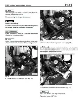
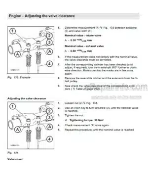
Check The Coolant Level
Checking The Condition Of The Coolant Hoses
Change The Coolant
Clean The Cooling Fins On Engine And Hydraulic Oil Cooler
Checking, Tensioning The V-Belt For The Generator System
Cleaning The Crankcase Ventilation
Check The Engine Mounts
Checking The Valve Clearance
Engine Problems
-MILLING DRIVE, DESCRIPTION
Milling Drive
-MILLING UNIT, DESCRIPTION
Description Of Milling Unit
-TRAVEL DRIVE, DESCRIPTION
Travel System
-CONVEYOR BELT, DESCRIPTION
Conveyor Belts
Folding / Unfolding The Loading Conveyor Belt
-HYDRAULICS
Hydraulic Circuit
Component Overview – Hydraulics
Description Of Travel Pump
View Of The Machine
Description Of Working Pump
View Of The Machine
Description Of Conveyor Belt Pump
View Of The Machine
Troubleshooting Axial Piston Pumps
Description Of Fan Pump
View Of The Machine
Description Of Travel Motor Bosch Rexroth
View Of The Machine
Check The Hydraulic Oil Level
Clean The Cooling Fins On Engine And Hydraulic Oil Cooler
Changing Hydraulic Oil And Breather Filter
Changing The Hydraulic Oil Filter
-HYDRAULICS – TRAVEL CIRCUIT
Description Of Driving
Description Of Crawler System
Description Of Steering
-HYDRAULICS – MILLING OPERATION
Description Of Clutch
View Of The Machine
Milling Box Hydraulics
View Of The Machine
-TESTS AND ADJUSTMENTS
Special Tools, Tests And Adjustments
Checking/Adjusting The Travel Pump
-CIRCUIT DIAGRAMS
Hydraulic Diagram
Electric Circuit Diagrams
What you get
You will receive PDF file with high-quality manual on your email immediately after the payment.


Reviews
There are no reviews yet.