


Factory Service Manual For Bomag Cold Milling Machine. Manual Contains Illustrations, Instructions, Diagrams For Step By Step Remove And Install, Assembly And Disassembly, Service, Inspection, Repair, Troubleshooting, Tune-Ups.
Format: PDF
Language: ENG
Pages: 872
Number: 00891613
Bookmarks: Yes
Searchable: Yes
Wiring Diagrams: Yes
Hydraulic Diagrams: Yes
Model
Bomag Cold Milling Machine
BM1000-30
BM1200-30
BM1300-30
S/N 821 836 17 ….
S/N 821 836 19 ….
S/N 821 836 18……
Contents
-GENERAL
Introduction
Safety Regulations
General Repair Instructions
Tightening Torques
-TECHNICAL DATA
Technical Data
-MAINTENANCE
General Notes On Maintenance
Fuels And Lubricants
Table Of Fuels And Lubricants
Running-In Instructions
Maintenance Table
-ELECTRICS
Understanding Circuit Diagrams
Terminal Designations In Wiring Diagram
Battery Ground And Analog Ground
Processor Signals
Current And Voltage
Pulse Width Modulation, Pwm
Resistance
Series / Parallel Connection
Ohm’s Law
Electrical Energy
Formula Diagram
Logical Base Gates
Metrology
Diodes, Relays, Fuses
Inductive Proximity Switches
Plug Connectors
Magnetic Coil Plug
Deutsch Plug, Series DT And DTM
Telemecanique Switch
Plugs And Terminals In Spring Clamping Technology
Batteries
Battery Service
Starting With Jump Wires
Component Overview
Control Consoles Operator’s Stand, 1200B1 And 100B6
Control Console Rear Right, 100B3
Control Console Rear Left, 100B2
Control Console Front Right, 100B4
Control Console Front Left, 100B1
Control Console For Auxiliary/Limp Home Control 100B5
Multi-Function Display, 290U1
Levelling Control Console, General
Automatic Milling Depth Control
Description Of Milling Depth Control
Viewing Switching States Of Switches And Valves
Work Parameters For Engine Load And Height Control
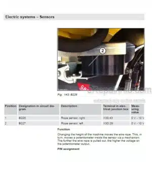
Rope Sensors For Height Control, 226.3R1 And 226.3R2
Operating Conditions For Height Regulation
Rope Sensor, Front Steering, 264R1
Cable Sensor, Rear Steering, 264R2
Operating Conditions For Rear Steering
Height Limitation, Rear
Operating Conditions For Rear Posts
Inclination Sensor For Height Regulation, 226.3U1
Limit Switch On Scraper, 214.1S1 And 214.1S2
Operating Conditions For Scraper
Water Sprinkling System
Operating Condition For Sprinkling System
Differential Pressure Switch For Hydraulic Oil
Speed Sensor, 206.5S1
Operating Conditions For Travel Drive
Engine Speed Sensor, 206.5S2
Fuses In Battery Box, 100B10
Terminal Box
Pin Assignment For Control
Operating Conditions For Breaker
Operating Conditions For Grade Shoes
Operating Condition For Milling Rotor Operation
Operating Conditions For Conveyor Belts
-ENGINE
General Information On Diesel Engine
Engine Attachment Parts
Engine Electrics
Checking The Cylinder Head Ground Cable
Engine Diagnostics Lamps, 282H1 And 282H2
General Notes On Flashing Codes
Table Of Flashing Codes
Check The Engine Oil Level
Change Engine Oil And Oil Filter Cartridge
Check, Clean The Water Separator
Change The Fuel Pre-Filter Cartridge
Replace The Fuel Filter Cartridge
Service The Combustion Air Filter
Checking The Combustion Air Filter
Check The Coolant Level
Checking The Condition Of The Coolant Hoses
Change The Coolant
Clean The Cooling Fins On Engine And Hydraulic Oil Cooler
Check, Tighten, Replace The Generator V-Belt
Checking, Tensioning The V-Belt For The Generator System
Cleaning The Crankcase Ventilation
Check The Engine Mounts
Checking The Valve Clearance
Engine Problems
-PUMP DRIVE
Pump Drive
Lubricating The Pillow Block For The Travel Pump Drive
Check, Tighten, Replace The Hydraulic Drive V-Belt
-MILLING DRIVE, MECHANICS
Milling Drive
Checking, Replacing The Milling Drum V-Belt
Change The Oil In The Milling Drum Reduction Gear
Oil Change In Milling Drum Bearing
Checking/Replacing Cutting Tools, Scraper
Retightening The Tool Holder Fastening Screws
Replacing Bases/Holders
Lubricating The Milling Drum
Lubricating The Dry Clutch
Checking The Wear Of The Friction Lining
Friction Lining / Replacing The Outer Discs
-CONVEYOR BELTS, MECHANICS
Conveyor Belts
Checking, Tightening The Conveyor Belts
Checking The Safety Ropes
Lubricating The Conveyor Belts
Folding / Unfolding The Loading Conveyor Belt
-TRAVEL DRIVE, MECHANICS
Travel System
Checking The Track Plates
Retightening The Track Shoe Fastening Screws
Checking The Track Drive
Lubricating The Travel Drive
Lubricating The Steering System
Oil Change In Track Drive Gear
-SERVICE TRAINING HYDRAULICS
Training
-HYDRAULIC CYLINDER
Repairing Hydraulic Cylinders
-SUPPLIERS DOCUMENTATION
Steering/Working Pump
Travel Pump
Conveyor Belt Pump
Travel Motor
Milling Drive
Travel Gear
Conveyor Belt Motor
Sprinkling Pump
Steering Valve
-CIRCUIT DIAGRAMS
Hydraulic Diagram
Wiring Diagram
What you get
You will receive PDF file with high-quality manual on your email immediately after the payment.


Reviews
There are no reviews yet.