


Factory Service Training For Bomag Tandem Vibratory Roller And Asphalt Manager. The Bomag Service Training Manual Describes The Disassembly, Dismantling, Assembly, Installation And Repair Of Components And Assemblies. Manual Addresses The Professionally Qualified Personnel Or The After Sales Service Of Bomag, And Should Be Of Help And Assistance In Correct And Efficient Repair And Maintenance Work.
Format: PDF
Language: English
Pages: 676
Number: 00891927 (april 2001)
Bookmarks: Yes
Searchable: Yes
Wiring Diagram: Yes
Hydraulic Diagram: Yes
Model
Bomag Tandem Vibratory Roller And Asphalt Manager
BW190AD-4AM
BW203AD-4AM
S/N 101 920 29 1001 > 101 920 29 1024
S/N 101 920 28 1001 > 101 920 28 1015
Contents
-GENERAL
Introduction
Safety Regulations
General Repair Instructions
Tightening Torques
-PIVOT STEERED TANDEM ROLLERS
Heavy Vibratory Rollers, Articulated
-TECHNICAL DATA
Technical Data
-MAINTENANCE
General Notes On Maintenance
Fuels And Lubricants
Table Of Fuels And Lubricants
Running-In Instructions
Maintenance Table
-ELECTRICS
Understanding Circuit Diagrams
Designation Of Components In The Wiring Diagram
Terminal Designations In Wiring Diagram
Circuit Symbols In The Circuit Diagram
Inductive Proximity Switch, B63
Angle Sensor On Travel Control Lever, B39
Pressure Sensor In Water Tank (R14)
Level Sensor In Diesel Tank (R03)
Hydraulic Oil Filter Differential Pressure Switch, B21
Float Switch In Water Tank, B33
Batteries
Battery Service, Check The Main Battery Switch
Main Battery Switch
Starting With Jump Wires
Potentiometer On Slewing Motor, B97
Acceleration Transducer
Speed Sensor, B15
Asphalt Temperature
Drivers Stand With Cabin
Fuses
MESX, B83
Electronic Control Units
Checking The Voltage Supply For The Control Unit
Diagnostics Concept
-ELECTRONIC MODULES
Electrics BAM
Electrics Module A03
Electrics Module A68
Electrics Module A71
Electric Module A72, Old Design
Electric Module A72
-ENGINE ELECTRICS
Emr3 System Components
Pin Assignment Of Engine Control Ed016 / Emr3
Rotary Speed Sensor For Camshaft
Rotary Speed Sensor For Crankshaft
Rail Pressure Sensor
Fuel Pressure Sensor
Fuel Control Unit
Injector
Oil Pressure Sensor
Sensor For Charge Air Temperature And Charge Air Pressure
EMR Coolant Temperature Sensor
Glow Plugs
Sensor, Water In Fuel
Rotary Switch For Engine Speed
Air Filter Vacuum Switch
Float Switch In Coolant Container
Charge Control Light, Operating Hour Meter
System Faults Indicated By Flashing Code
Flashing Code
Diagnose With Serdia
EMR3 List Of Fault Codes
Diagnose With Can-Bus
Diagnostics Interface
Generator
Electric Starter
-ASPHALT MANAGER
Asphalt Manager
-HYDRAULICS
Hydraulic Circuit
Travel Pump, A4VG56 HW
Vibration Pump, A10VG45 EZ
Overview Of Travel/Vibration Pump Connections
Travel Circuit
Vibration Circuit, Without Bam
Steering Circuit
Working Hydraulics
Fan Drive And Manifold Block With Thermostat
Check The Hydraulic Oil Level
Changing The Hydraulic Oil Filter
Changing Hydraulic Oil And Breather Filter
-TESTS AND ADJUSTMENTS
Special Tools, Tests And Adjustments
Checking The Rotation Speeds
Pressure Tests In The Travel Circuit
Checking / Adjusting The Neutral Positions Of The Travel Pump
Checking The Setting Of The High Pressure Relief Valves In The Travel Circuit
Pressure Tests In The Vibration Circuit
Check The Setting Of The High Pressure Relief Valves In The Vibration Circuit
Checking / Adjusting The Vibrator Shaft Speeds
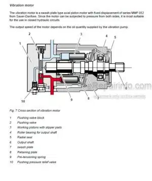
Check The Leakage Rate Of The Vibration Motor
Pressure Test In Steering Circuit
-TROUBLE SHOOTING
Trouble Shooting
Trouble Shooting Chart – Travel System
Trouble Shooting Chart – No Vibration
Trouble Shooting Chart Steering System
Troubleshooting Axial Piston Pumps
Engine Problems
-FLUSHING AND BLEEDING
Special Tools For Flushing
Flushing – General
Flushing Schematic For Front Drum Drive
Flushing The Front Drum Drive
Flushing Schematic For Rear Drum Drive System
Flushing The Rear Drum Drive
Flushing Schematic For Vibration Drive On Ad-Machines
Flushing The Vibration Circuit
Bleeding The Travel Circuit
Bleeding The Vibration Circuit
-ENGINE
Diesel Engine
Engine Description TCD 2012
Lubrication Oil Circuit TCD 2012/2013
Coolant Circuit TCD 2012 / 2013
Fuel System TCD 2012/2013
Deutz Common Rail (DCR) Injection System For TCD 2012 / 2013
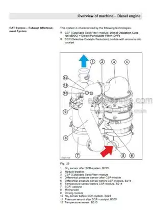
Exhaust Gas Recirculation TCD 2012 / 2013
Adjusting The Valve Clearance
Adjusting The Control Piston Play
General Trouble Shooting Chart TCD 2012 / 2013
Check The Engine Oil Level
Change The Engine Oil
Change The Engine Oil Filter Cartridge
Change The Fuel Filter Cartridge
Checking, Cleaning The Water Separator
Change The Fuel Pre-Filter Cartridge
Check The Coolant Level
Checking The Anti-Freeze Concentration
Change The Coolant
Checking The V-Belt, Tighten, If Necessary Replace The V-Belt
Check, Clean, Change The Combustion Air Filter
Replacing The Crank Case Ventilation Valve
Check The Engine Mounts
Electronic Injector Test EMR
Special Tools, Deutz Engine (TCD 2012 2V)
-AIR CONDITIONING SYSTEM
Physical Basics
Refrigerant R134A
Compressor Oil / Refrigeration Oil
Working Principle Of The Air Conditioning System
Monitoring Devices
Description Of Components
Measuring The Compressor Oil Level
Checking The Magnetic Clutch
Inspection And Maintenance Work
Checking, Tensioning, Replacing The Refrigerant Compressor V-Belt
Service The Air Conditioning
Drying And Evacuation
Emptying In Case Of Repair
Leak Test
Filling Instructions
Trouble Shooting In Refrigerant Circuit, Basic Principles
Trouble Shooting, Refrigerant Circuit Diagram
Trouble Shooting Procedure
Steam Table For R134A
-DRUM
Repair Overview AD-Drum
Repair Overview AM-Drum
-CIRCUIT DIAGRAMS
Hydraulic Diagram
Wiring Diagram
What you get
You will receive PDF file with high-quality manual on your email immediately after the payment.


Reviews
There are no reviews yet.