


Factory Service Manual For Case 1400 Cotton Harvester. Manual Contains Illustrations, Instructions, Diagrams For Step By Step Remove And Install, Assembly And Disassembly, Service, Inspection, Repair, Troubleshooting, Tune-Ups.
Format: PDF
Language: English
Pages: 210
Number: GSS-1502
Bookmarks: Yes
Wiring Diagrams: Yes
Hydraulic Diagrams: Yes
Model
Case Cotton Harvester
1400
Contents
WORK SAFELY – FOLLOW THESE RULES
STANDARD TORQUE DATA FOR NUTS AND BOLTS
METRIC CONVERSION TABLES
STANDARD TORQUE DATA FOR HYDRAULIC TUBES AND FITTINGS
FLANGETTE BEARING INSTALLATION
SPECIAL SERVICE TOOLS REQUIRED
-GUIDE WHEEL AXLE AND WHEELS
General Description
Pressurizer Filter
Blower Motor
Heater Core
Windshield Wiper Motor
Digital “Read Out” Monitor
Troubleshooting the Digital Monitor
Air Conditioning System
Specifications
Special Torques
Service Tools Required
Evaporator
Receiver-Dryer Assembly
Condenser
Compressor
Troubleshooting
-HYDROSTATIC POWER STEERING
General Description
Principles of Operation
Control Valve
Metering Section
Rotor Operation and the Metering Element
Manual Operation
Steering Hand Pump
Steering Pump Seal Replacement
Steering Check Valve
Venting the Steering System
Steering Cylinder
-ENGINE
Specifications
Special Torques
-FUEL SYSTEM
Fuel Tank
-ELECTRICAL
Specifications
Wiring Diagram
Sensors
Transducer
Neutral Starting Switch Adjustment
Fuse, Cartridge Type
-COOLING SYSTEM
Radiator
-UNIT MAIN DRIVE SHAFT
Unit Main Drive Shaft
Auger Drive Shaft
Green Boll Auger
Drive Belt Replacement
-HYDROSTATIC DRIVE
Specifications
Adjusting the Propulsion Control Lever (In conjunction with Calibrating the Digital Monitor)
Operating Principles of the Foot-N-Inch Valve
Adjusting the Foot-N-Inch Pedal
Test Procedures
Purging the System
-TRANSMISSION AND DIFFERENTIAL
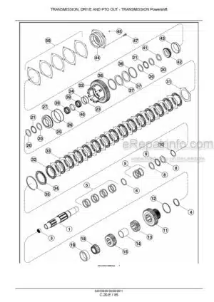
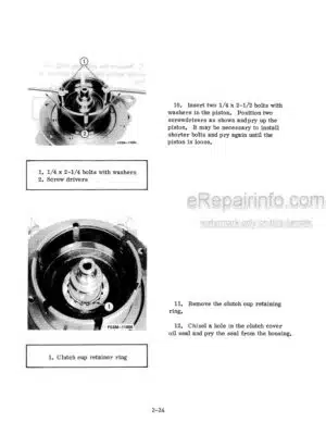
Transmission
Transmission Gear Shift Lever Adjustment
-FINAL DRIVES
Final Drive
Drive Wheel Stud Replacement
Replacing Final Drive Housing-To-Axle Studs
-BRAKES
General Description
Master Brake Cylinder
Brake Cylinders
Servicing the Brake Disc
Bleeding the System
Brake Adjustment
Brake Housing
Parking Brake
-CROSS AUGER HEADER AND BRUSH ROLL UNITS
Cross Auger Header
Automatic Height Sensing Adjustment
Brush Roll Units
Unit Drive Joint Assembly
Cross Auger Drive Pulley
Cross Auger Service
Unit Drive Pulleys
Belt Replacement and Adjustment
Troubleshooting
-HYDRAULIC SYSTEM
Basic Hydraulic System
Unit Control Valve Operating Principles
Schematics of Flow
Reservoir
Component Service
Rotary Flow Divider to Control Valve Operating Units
Service the Automatic Height Control Valve
Basket Compactor and Boll Box Valves
Troubleshooting
-TESTING HYDRAULIC SYSTEM
Testing 1136 litres (3 gpm) Circuit
Testing 5678 litres (15 gpm) Circuit
Testing the Steering Circuit at the Cylinder
-FAN ASSEMBLY
Fan Assembly
What you get
You will receive PDF file with high-quality manual on your email immediately after the payment.


Reviews
There are no reviews yet.