Factory Service Manual For Case Tractors Chassis. Manual Contains Illustrations, Instructions, Diagrams For Step By Step Remove And Install, Assembly And Disassembly, Service, Inspection, Repair, Troubleshooting, Tune-Ups.
Format: PDF
Language: English
Pages: 339
Number: GSS14451
Bookmarks: Yes
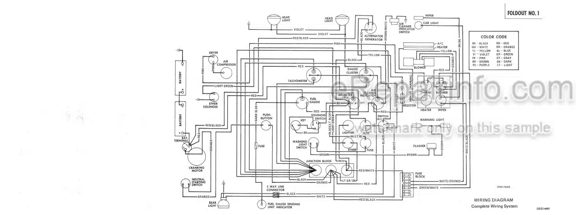
Wiring Diagrams: Yes
Hydraulic Diagrams: Yes
Model
Case Chassis Tractor
4366
4386
4568
4586
Contents
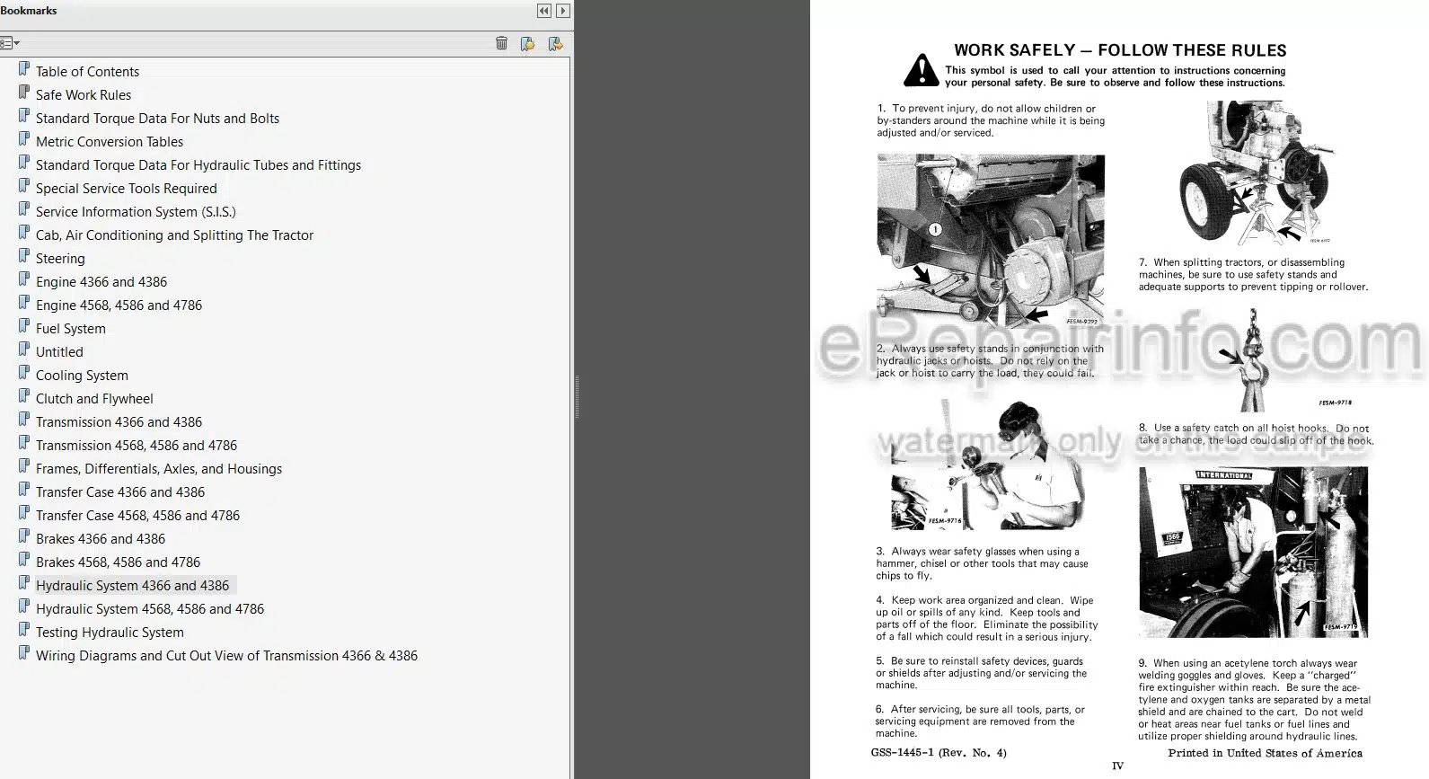
SAFE WORK RULES
STANDARD TORQUE DATA FOR NUTS AND BOLTS
METRIC CONVERSION TABLES
STANDARD TORQUE DATA FOR HYDRAULIC TUBES AND FITTINGS
SPECIAL SERVICE TOOLS REQUIRED
SERVICE INFORMATION SYSTEM (SIS)
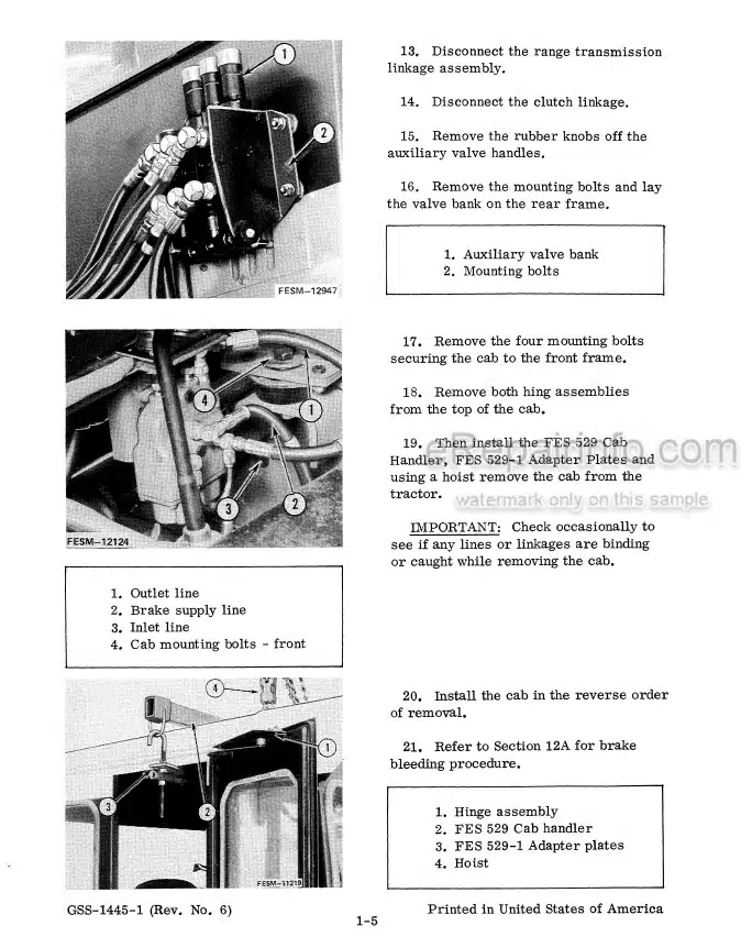
-CAB, AIR CONDITIONING AND SPLITTING THE TRACTOR
Cab
Air Conditioning
Splitting The Tractor
Adjustments
-STEERING
Power Steering Hand Pump
Hydraulic Cylinders
-ENGINE 4366 AND 4386
Specifications
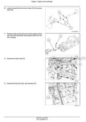
Removal
-ENGINE 4568,4586 AND 4786
Specifications
Engine Removal
Oil Pan Removal
-FUEL SYSTEM
Specifications
Fuel Tank
Welding Repairs On Diesel Fuel Tanks
-UNTITLED
Specifications
Digital Monitor 4386, 4586 S/N 1500 And Below
Transducer
Instrument Gauge And/Or Light Removal
Troubleshooting The Low Oil Level Warning Indicator
Digital Data Center (4386, 4586 And 4786)
Early Warning System
-COOLING SYSTEM
Specifications
Radiator
-CLUTCH AND FLYWHEEL
Specifications
Flat Type Clutch Assembly
Pot Type Clutch Assembly
Removal
Disassembly
Inspection
Reassembly
Installation
Clutch Adjustment
Release Bearing Lube Hose Installation
-TRANSMISSION 4366 AND 4386
Specifications
Special Torques
Transmission Removal
Removal Of Components
Timing The Auxiliary Shafts
Transmission Case Assembly Introduction
Left Reverse Idler Gear Assembly
Mainshaft
Reassembly And Installation Of The Left And
Right Reverse Idler Gear Assembly
Countershaft Bearings
Countershaft
Timing And Installation Of The Countershaft Assemblies
Timing Of The Left Countershaft
Timing And Installation Of The Right Countershaft Assembly
Mainshaft Drive Gear
Mainshaft Drive Gear Assembly
Timing And Installation Of The Drive Gear Assembly
Installing The Transmission To The Engine And Flywheel Housing
-TRANSMISSION 4568,4586 AND 4786
Specifications
Special Torques
Transmission Removal
Removal Of The Components
Transmission Case Disassembly
Mainshaft Installation
-FRAMES, DIFFERENTIALS, AXLES, AND HOUSINGS
Specifications
Special Torques
Introduction
Rear Frame (All Models)
Differential (4366, 4386 And 4586)
Axle And Bull Pinion Shaft (All Models)
Front Frame Removal (All Models)
Application Of Loctite 515
Gasket Eliminator Sealant
Differential (4786)
Axle (4786)
Planetary (4786)
-TRANSFER CASE 4366 AND 4386
Specifications
Special Torques
Transfer Case
-TRANSFER CASE 4568,4586 AND 4786
Specifications
Special Torques
Transfer Case
-BRAKES 4366 AND 4386
Specifications
Introduction
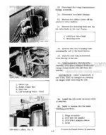
Park Brake Removal
Hydraulic Caliper Type Brake
Brake Disc Removal
Procedure For Bleeding Brakes
Adjustments
Power Hydraulic Multi-Disc Brakes 4386 & 4586
Serial Number 1501 And Above
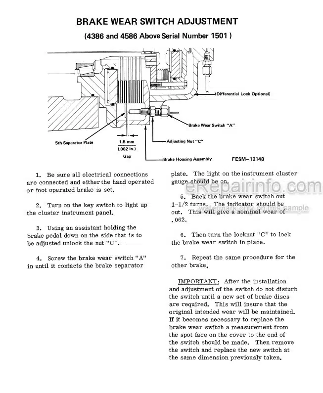
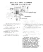
Brake Wear Switch Adjustment (4386 & 4586 Above Sn 1500)
-BRAKES 4568,4586 AND 4786
Specifications
Special Torques
Hand Brake Removal
Hydraulic Caliper Type Brake
Adjustment
Procedure For Bleeding Brakes
Brake Wear Switch Adjustment
Power Brake Valve
4786 Brake Removal And Disassembly
4786 Brake Bleeding Procedure
-HYDRAULIC SYSTEM 4366 AND 4386
Specifications
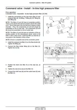
Basic Hydraulic System
Hydraulic Pumps
Auxiliary Valve Operation
System Relief Valve
Power Steering System
Hydraulic System Schematic
-HYDRAULIC SYSTEM 4568,4586 AND 4786
Specifications
Basic Hydraulic System
Auxiliary Valves Operation
System Relief Valve
Power Steering System
Hydraulic Schematic
Hitch Components
Hydraulic Pump
-TESTING HYDRAULIC SYSTEM
Specifications
Trouble Shooting The Basic Hydraulic System
Trouble Shooting The Power Steering System
Transmission Pump
Checking The Oil Cooler By Pass Valve 4568, 4586 And 4786
Checking The Steering Relief Valve
Checking The Brake Regulator Pressure 4786 Only
Auxiliary Valves
-WIRING DIAGRAMS AND CUT OUT VIEW OF TRANSMISSION 4366 & 4386
What you get
You will receive PDF file with high-quality manual on your email immediately after the payment.




Reviews
There are no reviews yet.