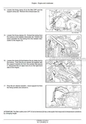
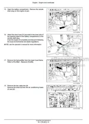
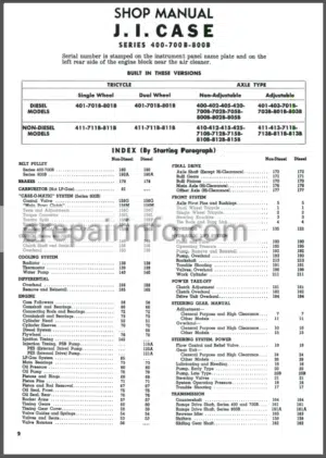
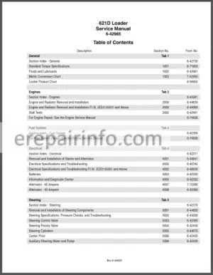
Factory Service Manual For Case Diesel Tractor And Engine. Manual Contains Illustrations, Instructions, Diagrams For Step By Step Remove And Install, Assembly And Disassembly, Service, Inspection, Repair, Troubleshooting, Tune-Ups.
Format: PDF
Language: English
Pages: 587
Number: 5675
Bookmarks: Yes
Model
Case Diesel Tractor And Engine
500 Series
Contents
PROFIT THROUGH “QUALIFIED CASE DIESEL SERVICE”
REQUIREMENTS FOR A “QUALIFIED CASE DIESEL SERVICE DEPARTMENT”
SERVICE AND WARRANTY POLICY BETWEEN CASE DEALERS AND OFFICIAL AMERICAN BOSCH DIESEL FUEL INJECTION SERVICE STATIONS
OUTLINE FOR PERFORMING A PERIODIC CHECK-UP ON A “500” SERIES CASE DIESEL TRACTOR
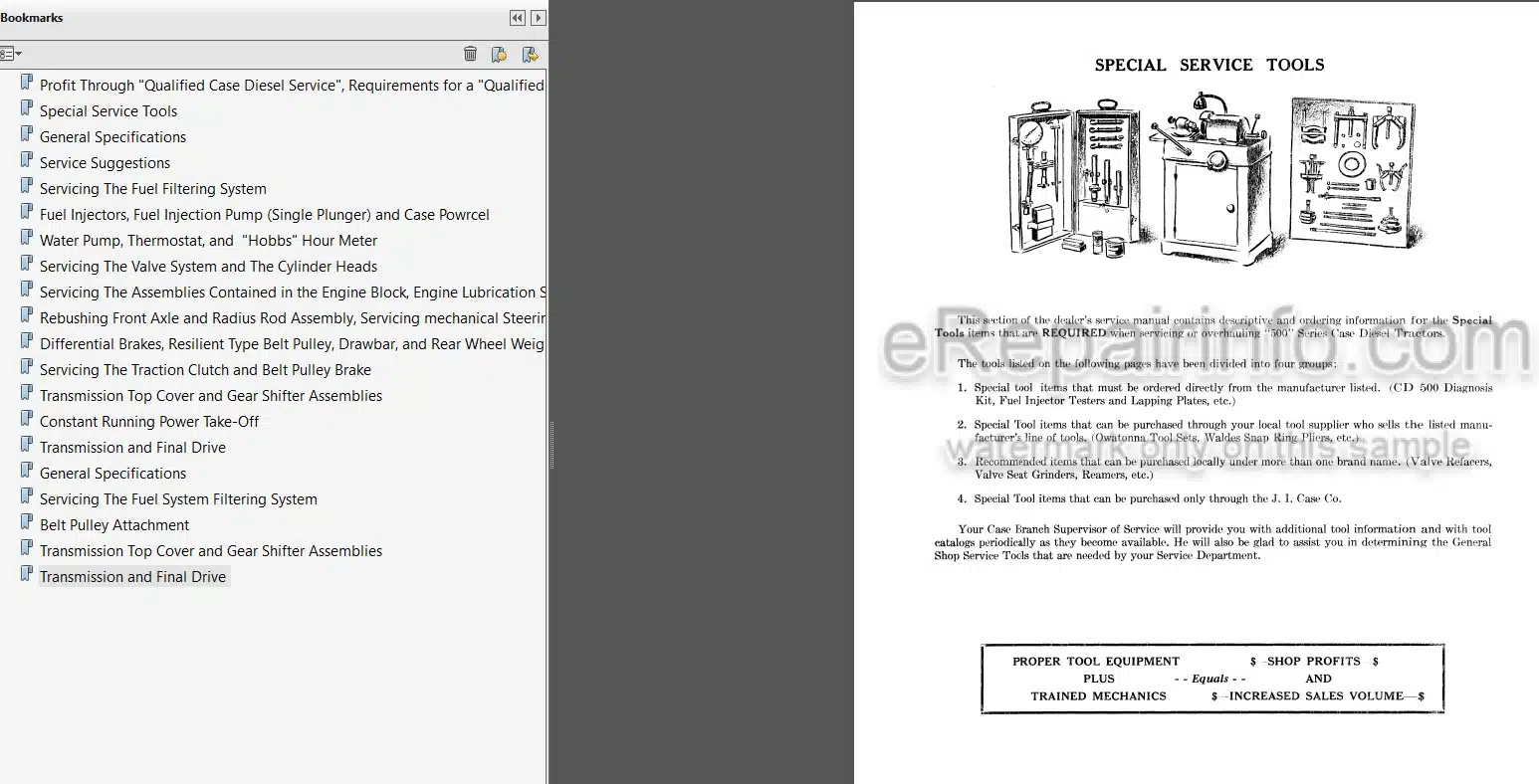
-SPECIAL SERVICE TOOLS
Introduction
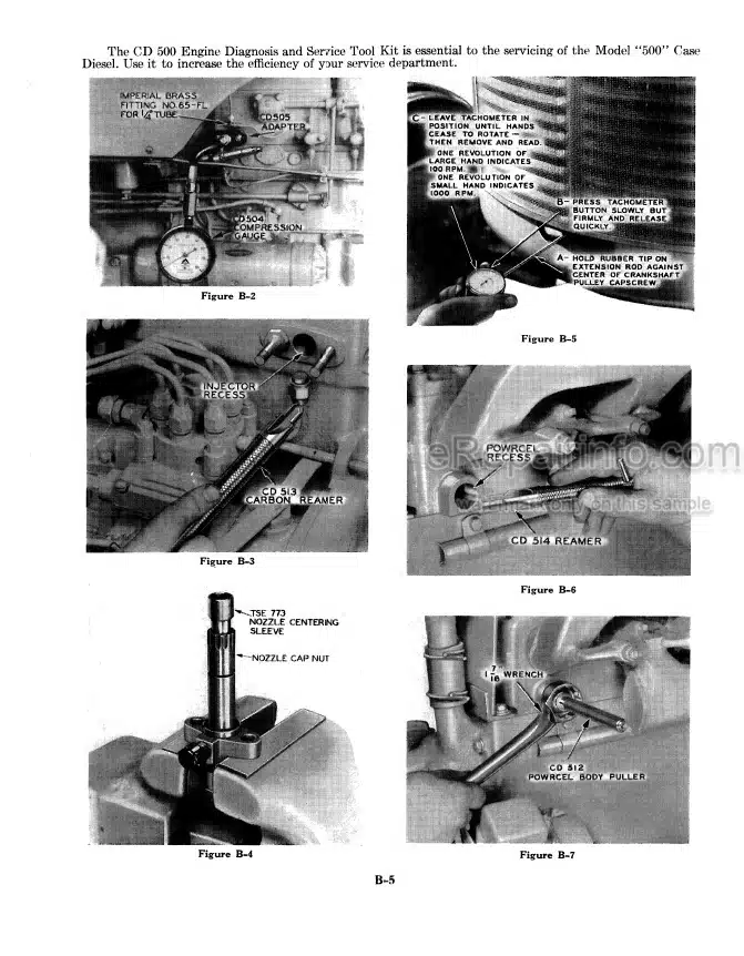
Model “500” Case Diesel Engine Diagnosis and Service Tool Kit
Fuel Injector Test Stand and Lapping Plate
Owatonna Service Tool Set
Special Snap Ring Tools (Purchased Locally)
Valve and Cylinder Head Service Tools
Miscellaneous Shop Service Tools (Purchased Locally)
Special Wrenches (Purchased Through J I Case Company or Local Snap-On Tool Company Representatives)
Special Service Tools (Purchased Through J I Case Company)
Special Hydraulic Service Tools (Purchased Through J I Case Company)
-GENERAL SPECIFICATIONS
General Dimensions, Speeds, Weights, and Capacities
General Engine Specifications
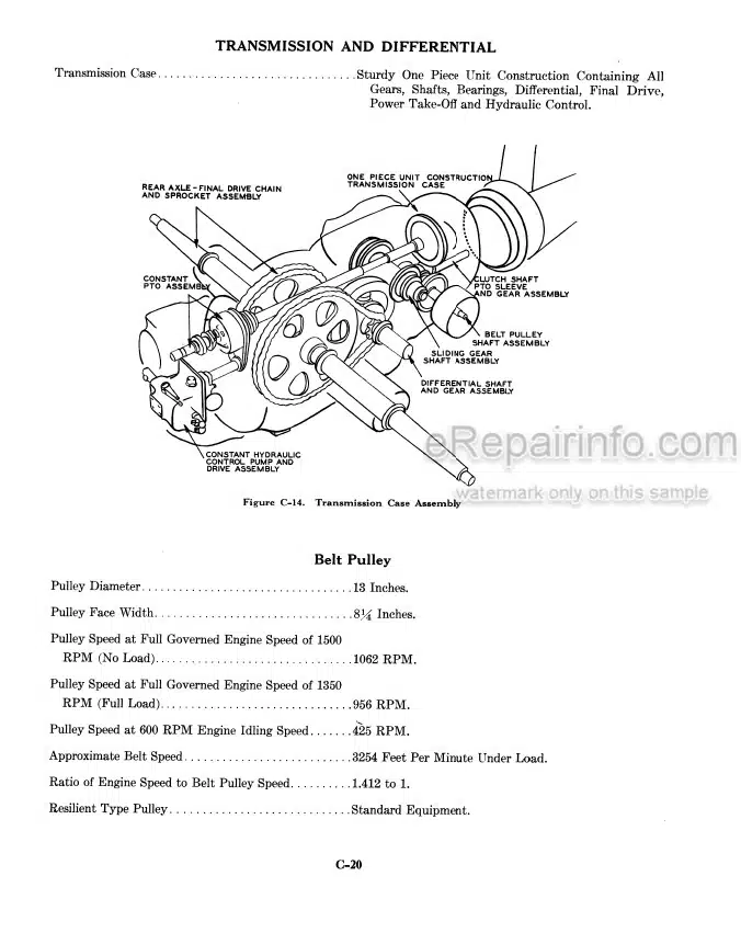
Transmission and Differential
Tightening Specifications
-SERVICE SUGGESTIONS
Engine Will Not Start or is Difficult to Start
Smoke From Engine Exhaust
Excessive Fuel Consumption
Excessive Oil Consumption
Contamination in the Crankcase Oil
Engine Will Not Stop When Fuel Is Shut Off
Traction Clutch
Generator
Starting Motor
Noise, Knocks and Vibration
Difficulty in Shifting
Constant Running Power Take-off
Hydraulic Power Steering
Engine Hour Meter
Oil Leakage
-SERVICING THE FUEL FILTERING SYSTEM
Fuel Flow Diagram
General Description of Fuel Filtering System
Checking Fuel Flow Through Filtering System
Visual Inspection of Fuel System
Servicing Fuel Lincs
Bleeding the Fuel System
Fuel Tank Breather Air Filter
Fuel Tank Screen
Fuel Tank Water Trap
Cleaning the Fuel Tank
Servicing First Stage Filter
Servicing Second Stage Filter
Servicing Final Fuel Filter and Pressure Relief Valve
-FUEL INJECTORS, FUEL INJECTION PUMP (SINGLE PLUNGER) AND CASE POWRCEL
Fuel Injectors
American Bosch Model PSB Single Plunger Fuel Injection Pump
Case Powrcel
-WATER PUMP, THERMOSTAT, AND “HOBBS” HOUR METER
Water Pump
Thermostat
Hobbs Hour Meter
-SERVICING THE VALVE SYSTEM AND THE CYLINDER HEADS
General Description of Valve System and Cylinder Head
Service Operations That Can Be Performed Without Removing
Service Operations That Require Removal of Cylinder Head From Engine
Hood Removal and Installation
Valve (/Over Removal and Installation
Crankcase Breathers
Valve Tappet Clearance Adjustment
Rocker Arm and Decompressor Assembly
Manifolds (Intake, Exhaust and Water)
Cylinder Head Removal and Installation
Servicing the Valves and Valve Seats
-SERVICING THE ASSEMBLIES CONTAINED IN THE ENGINE BLOCK
Engine Lubrication System
Pistons – Connecting Rods and Cylinder Sleeves
Crankshaft – Main Bearings and Flywheel
Camshaft and Push Rod Lifters
Fuel Injection Pump Drive and Timing Gear Train
REBUSHING FRONT AXLE AND RADIUS ROD ASSEMBLY
SERVICING MECHANICAL STEERING ASSEMBLIES
SERVICING POWER STEERING
DIFFERENTIAL BRAKES
RESILIENT TYPE BELT PULLEY
DRAWBAR
REAR WHEEL WEIGHTS
-SERVICING THE TRACTION CLUTCH AND BELT PULLEY BRAKE
Clutch Specifications
Reassembling the Traction Clutch on the Tractor
Servicing the Traction Clutch
Traction Clutch and Belt Pulley Brake
-TRANSMISSION TOP COVER AND GEAR SHIFTER ASSEMBLIES
Removing and Servicing the Gear Shift Lever
Servicing the Shifter Assembly
Transmission Top Cover
-CONSTANT RUNNING POWER TAKE-OFF
Constant Running Power Take-off
Crankcase Oil Passing Into The Transmission and Transmission
-TRANSMISSION AND FINAL DRIVE
Transmission and Final Drive
-GENERAL SPECIFICATIONS
Diesel Engine
Spark Ignition Engine
-SERVICING THE FUEL SYSTEM FILTERING SYSTEM
Fuel Flow Diagram
General Description of Fuel Filtering System
Checking Fuel Flow Through Filtering System
Visual Inspection of Fuel System
Servicing Fuel Lines
Bleeding the Fuel System Fuel Tank Breather Air Filter Fuel Tank Screen
Fuel Tank Water Trap
Cleaning the Fuel Tank
Gum and Varnish In the Fuel
Servicing First Stage Filter
Servicing Second Stage Filter
Servicing Final Fuel Filter and Pressure Relief Valve
-BELT PULLEY ATTACHMENT
Servicing the Belt Pulley Attachment
Tools Required
Service Diagnosis
Removing the Belt Pulley Attachment
Disassembly of the Belt, Pulley
Replacing the Pilot Bushing in the First Reduction Shaft
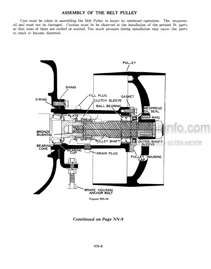
Assembly of the Belt Pulley
Assembly of the Belt Pulley Clutch
Installing the Belt Pulley Attachment, on Case “GOO” Series Tractors
-TRANSMISSION TOP COVER AND GEAR SHIFTER ASSEMBLIES
Transmission Top Cover
Removing and Servicing the Gear Shift Lever
Transmission Shifter Assemblies
-TRANSMISSION AND FINAL DRIVE
Transmission And Final Drive
Sliding gear Shaft
First Reduction Shaft
Reverse Idler Gear
Differential Gear Assembly
Systematic Checks for Isolating Transmission Noise
Rear Axle Assembly
What you get
You will receive PDF file with high-quality manual on your email immediately after the payment.



Reviews
There are no reviews yet.