


Factory Service Manual For Case Telescopic Handler. Manual Contains Illustrations, Instructions, Diagrams For Step By Step Remove And Install, Assembly And Disassembly, Service, Inspection, Repair, Troubleshooting, Tune-Ups.
Format: PDF
Language: English
Pages:
Number:
Bookmarks: Yes
Wiring Diagrams: Yes
Hydraulic Diagrams: Yes
Model
Case Telescopic Handler
686G
686GXR
688G
Series 2
Contents
-GENERAL
Standard Torque Specification
Fluids and Lubricants
Safety and General Information
Loctite Product Chart
-ENGINE
Diesel Engine Specifications
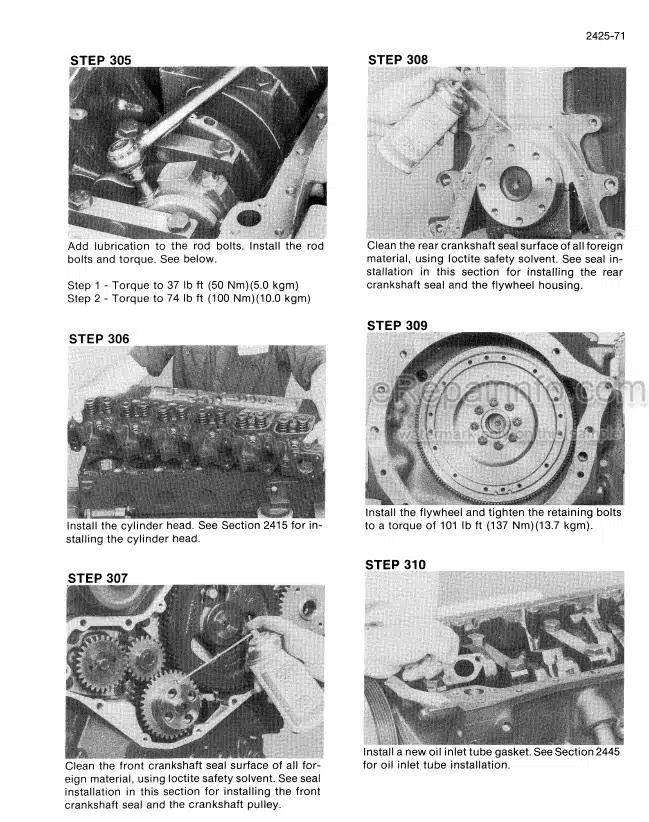
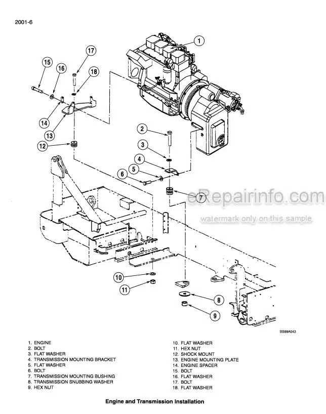
Engine and Transmission Removal and Installation
Engine Troubleshooting
-FUEL SYSTEM
-ELECTRICAL
Electrical System General
Electrical Schematics and Troubleshooting
Electrical Gauges and Senders
Alternator
-STEERING
How It Works
Steering Specifications
Steering Troubleshooting
Steering Pump and Steering Column
Steering Selector Valve
Steering Priority Valve
-POWER TRAIN
How It Works
Removal and Installation of Power Train Components
Transmission Specifications and Troubleshooting
Drive Axle
-BRAKES
How It Works
Brake System Specifications
Brake System Troubleshooting
Brake System Removal and Installation of Components
-HYDRAULICS
How It Works
Hydraulic Specifications, Schematics and Troubleshooting
Hydraulic Specifications, Schematics and Troubleshooting
686GXR PIN JFE0001848 and after, 688G PIN JFE0003613 and after
Removal and Installation of Hydraulic Components
Hydraulic Cylinders
Hydraulic and Fuel Tanks
-MOUNTED EQUIPMENT AND CHASSIS
How It Works
Specifications, and Troubleshooting
Removal and Installation of Boom Components
Electrical Schematic and Hydraulic Schematic Foldout – 686G686GXR and 688G
Electrical Schematic and Hydraulic Schematic Foldout – 686GXR Series 2 Machines
PIN JFE0001848 and After and 688G Series 2 Machines PIN JFE0003613 and After
-DRIVE AXLE TYPE 212
Introduction
Maintenance and Lubricant
Notes on Safety Precautions
Checking Wear and Replacing The Braking Disks
Steering Case
U-Joint
Planetary Reduction
Steering Cylinder
Differential Unit
Bevel Pinion
Special Tools
Troubleshooting
Optionals
External Hydraulic Negative Brake
External Hydraulic Negative Brake With Quick Release
Incoming Drum Brake
4″ Incoming Brake (2 and 3 Function Versions)
Limited Slip Differential Unit (25% and 45%)
Hydraulic Differential Lock
Incorporated Reduction Gear and Pinion (602)
-T12000 POWERSHIFT TRANSMISSION
T12000 Transmission Assembly
How The Units Operate
Sectional Views And Parts Identification
Disassembly Of Transmission
Reassembly Of Transmission
Clutch Engagement (Power Flow) 4 And 6 Speed
Clutch Engagement (Power Flow) 3 Speed
Drive Plate Installation
Transmission To Engine Installation Procedure
Specifications And Service Data
Servicing Machine After Transmission Overhaul
External Plumbing And Pressure Check Points
Cleaning And Inspection
Parking Brake Service
Troubleshooting Guide
Converter Stall Procedure
Electric Solenoid Control Wiring Diagram
What you get
You will receive PDF file with high-quality manual on your email immediately after the payment.


Reviews
There are no reviews yet.