


Factory Repair Manual For Caterpillar 232B2 Skid Steer Loader. Illustrations, instructions, diagrams for step by step remove and install, assembly and disassembly, service, inspection, repair, troubleshooting, tune-ups.
Format: PDF
Language: English
Pages: 4053
Bookmarks: Yes
Searchable: Yes
Model
Caterpillar 232B2
SCH02475-UP
Contents
-AIR INLET AND EXHAUST SYSTEM
Air Inlet and Exhaust System
Air Inlet and Exhaust System – Inspect
Exhaust Temperature – Test
Air Inlet and Exhaust System – Inspect
Wastegate – Test
Exhaust Temperature – Test
Air Cleaner – Remove and Install
Exhaust Manifold – Remove and Install
Exhaust Manifold
Exhaust Manifold – Remove and Install
Muffler – Remove and Install Turbocharger
Turbocharger – Remove and Install
-BASIC ENGINE
Basic Engine
Finding Top Center Position for No. 1 Piston
Fuel Injection Nozzle – Test
Gear Group (Front) – Time
Engine Crankcase Pressure (Blowby) – Test
Compression – Test
Engine Valve Lash – InspectAdjust
Valve Depth – Inspect
Valve Guide – Inspect
Excessive Bearing Wear – Inspect
Piston Ring Groove – Inspect
Connecting Rod – Inspect
Connecting Rod Bearings – Inspect
Main Bearings – Inspect
Cylinder Block – Inspect
Cylinder Head – Inspect
Piston Height – Inspect
Flywheel – Inspect
Flywheel Housing – Inspect
Gear Group – Inspect
Finding Top Center Position for No. 1 Piston
Gear Group (Front) – Time
Engine Crankcase Pressure (Blowby) – Test
Compression – Test
Engine Valve Lash – InspectAdjust
Valve Depth – Inspect
Valve Guide – Inspect
Excessive Bearing Wear – Inspect
Piston Ring Groove – Inspect
Connecting Rod – Inspect
Connecting Rod Bearings – Inspect
Main Bearings – Inspect
Cylinder Block – Inspect
Cylinder Head – Inspect
Piston Height – Inspect
Flywheel – Inspect
Flywheel Housing – Inspect
Gear Group – Inspect
Belt Tension Chart
Camshaft
Camshaft
Camshaft – Remove
Camshaft – Disassemble
Camshaft – Assemble
Camshaft – Install
Crankshaft
Connecting Rod Bearing Journal
Main Bearing Journal
Crankshaft
Connecting Rod Bearing Journal
Main Bearing Journal
Crankshaft Rear Seal – Remove
Crankshaft Rear Seal – Install
Crankshaft – Remove
Crankshaft – Install
Bearing Clearance – Check
Crankshaft Rear Seal – Remove and Install
Crankshaft Wear Sleeve (Rear) – Remove and Install
Crankshaft Pulley – Remove and Install
Crankshaft Front Seal – Remove and Install
Crankshaft Main Bearings – Remove
Crankshaft Main Bearings – Install
Crankshaft – Remove
Crankshaft – Install
Bearing Clearance – Check
Cylinder Blodcpdf
Main Bearing Journal
Cylinder Block
Main Bearing Journal
Crankshaft Main Bearings – Remove
Crankshaft Main Bearings – Install
Bearing Clearance – Check
Crankshaft Main Bearings – Remove
Crankshaft Main Bearings – Install
Bearing Clearance – Check
Fuel Injection Nozzles
Cylinder Head Valves
Cylinder Head
Fuel Injection Nozzles
Cylinder Head Valves
Cylinder Head
Inlet and Exhaust Valve Springs – Remove and Install
Inlet and Exhaust Valves – Remove and Install
Cylinder Head – Remove
Cylinder Head – Install
Inlet and Exhaust Valve Springs – Remove and Install
Inlet and Exhaust Valves – Remove and Install
Cylinder Head – Remove
Cylinder Head – Install
Fan Drive
Fan Drive
Flywheel
Flywheel Housing
Flywheel – Remove
Flywheel – Install
Flywheel – Remove
Flywheel – Install
Gear Group (Front)
Gear Group (Front)
Flywheel Housing – Remove and Install
Flywheel Housing – Remove and Install – Engines with Flywheel Housing and Back Plate
Housing (Front)
Housing (Front) – Remove
Housing (Front) – Install
Housing (Front) – Disassemble
Housing (Front) – Assemble
Engine Lifting Bracket
Engine Oil Pan
Engine Oil Pan – Remove and Install
Engine Oil Pan – Remove and Install
Connecting Rod Bearing Journal
Connecting Rod
Piston and Rings
Connecting Rod Bearing Journal
Connecting Rod
Piston and Rings
Pistons and Connecting Rods – Remove
Pistons and Connecting Rods – Disassemble
Pistons and Connecting Rods – Assemble
Pistons and Connecting Rods – Install
Connecting Rod Bearings – Remove
Connecting Rod Bearings – Install
Bearing Clearance – Check
Pistons and Connecting Rods – Remove
Pistons and Connecting Rods – Disassemble
Pistons and Connecting Rods – Assemble
Pistons and Connecting Rods – Install
Connecting Rod Bearings – Remove – Connecting rods in position
Connecting Rod Bearings – Install – Connecting rods in position
Bearing Clearance – Check
Crankshaft Pulley
Crankshaft Pulley – Remove and Install
Belt Tension Chart
Belt Tension Chart
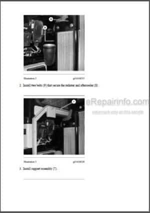
V-Belts – Remove and Install
V-Belts – Remove and Install
Rocker Shaft
Valve Mechanism Cover
Lifter Group.Ddf
Rocker Shaft
Valve Mechanism Cover
Valve Mechanism Cover – Remove and Install
Rocker Shaft and Pushrod – Remove
Rocker Shaft – Disassemble
Rocker Shaft – Assemble
Rocker Shaft and Pushrod – Install
Lifter Group – Remove and Install
-COOLING SYSTEM
Cooling System
Cooling System – Check – Overheating
Cooling System – Inspect
Cooling System – Test
Water Temperature Regulator – Test
Water Pump – Inspect
Cooling System – Check – Overheating
Cooling System – Inspect
Cooling System – Test
Water Temperature Regulator – Test
Water Pump – Inspect
Radiator and Hydraulic Oil Cooler
Radiator and Hydraulic Oil Cooler (Fan) Gear Motor (Fan)
Gear Motor (Fan) – Demand
Fan Drive
Fan – Remove and Install
Water Temperature Regulator
Water Temperature Regulator – Remove and Install
Water Temperature Regulator Housing – Remove and Install
Water Temperature Regulator – Remove and Install
Water Pump – Remove
Water Pump – Install
Water Pump – Remove and Install
Radiator and Hydraulic Oil Cooler
Radiator and Hydraulic Oil Cooler (Fan)
Radiator and Hydraulic Oil Cooler – Remove
Radiator and Hydraulic Oil Cooler – Install
Water Temperature Regulator
Water Temperature Regulator – Remove and Install
Water Temperature Regulator Housing – Remove and Install
Water Temperature Regulator – Remove and Install
-ELECTRICAL AND STARTING SYSTEM
General Information
Normal Operation
Electronic Control Module (ECM)
Solenoid Valves
Cat Data Linkpdf
Related Components
General Information
Normal Operation
Engine Start Interlock
Hydrostatic System Interlock and Parking Brake Interlock Work Tool Interlodcpdf
Diagnostic Operation
Electronic Control Module (ECM)
Solenoid Valve
Relays
Related Components
Electrical System
Pressure Switch (Refrigerant)
Electrical System
Getting Started
Enable Program
Verify Machine Records and Ownership
Manage Users
Product Link Installation
Setup Subscriptions
Administration
Manage Equipment Groups
Manage Hardware
Manage Event Tracking
Upload Data
Manage Major RepairTracking
Manage Time Fence and Geographic Fence
Manage Planned Maintenance
Preferences
Preference Detail
Asset Watch
Time Fence and Geographic Fence
Maintenance Watch
Planned Maintenance
Major Repair
Health Watch
Fuel Results
Fault Codes
Reports
Product Usage
Product Monitoring
Operation and Maintenance Manual
Equipment Usage
Active Fleetpdf
General Information
Getting Started
Verify Machine Records and Ownership
Manage Users
Product Link Installation
Administration
Manage Equipment Groups
Manage Hardware
Manage Event Tracking
Upload Data
Manage Major Repair Tracking
Manage Time Fence and Geographic Fence
Manage Planned Maintenance
Preferences
Preference Detail
Asset Watch
Time Fence and Geographic Fence
Maintenance Watch
Planned Maintenance
Major Repair
Health Watch
Fuel Results
Fault Codes
Reports
Product Usage
Product Monitoring
Operation and Maintenance Manual
Equipment Usage
General Information
System Overview
Normal Operation
Operation of Status Indicator
Key Information
Scheduled Access – Security System Bypass Times
Diagnostic Operation
Events
Protected Functions
Service Operation Using Machine Security System
Service Operation Using Service Tool
Electronic Control Module (ECM)
System Components.Ddf
Cat Data Link
System Overview
System Components
Installation Parameters Configure
Configuration
Spare Input Configure
Commands
System Overview
System Components
Spare Inputs
Configuration
Installation Parameters Configure
Report Parameters Configure
Wireless Service Configure
Spare Input Configure
Commands
Wiring Harness (Open Circuit) – Test
Wiring Harness (Short Circuit) – Test
Electronic Control Module (ECM) – Flash Program
Electronic Control Module (ECM) – Replace
Glossary of Electrical Terms
System Schematic
Electronic Control Module (ECM) – Replace
Glossary of Electrical Terms
System Schematic
Electronic Control Module (ECM) – Replace
Glossary of Electrical Terms
System Schematic
Alternator – Test
Battery – Test
Charging System – Test
Coolant Temperature Switch – Test
Electric Starting System – Test
Engine Oil Pressure Switch – Test
Fuel Shutoff Solenoid – Test
Glow Plugs – Test
Alternator – Test
Battery – Test
Charging System – Test
Coolant Temperature Switch – Test
Electric Starting System – Test
Engine Oil Pressure Switch – Test
Fuel Shutoff Solenoid – Test
Glow Plugs – Test
General Information
Product Identification Number – Program
Key – Program
System Disarm – Program – Security System Bypass
Factory Password – Obtain
Time – Set
Software – Uninstall – Immobilizer Feature
Electrical Connector – Inspect
Electronic Control Module (ECM) – Flash Program
Electronic Control Module (ECM) – Replace
Glossary of Terms
System Schematic
Electronic Control Module (ECM) – Flash Program
Electronic Control Module (ECM) – Replace
Electrical Connector – Inspect
Wiring Harness (Open Circuit) – Test
Wiring Harness (Short Circuit) – Test
Specifications
System Schematic
Electronic Control Module (ECM) – Flash Program
Electronic Control Module (ECM) – Replace
Electrical Connector – Inspect
Wiring Harness (Open Circuit) – Test
Wiring Harness (Short Circuit) – Test
Specifications
System Schematic
General Information
Service Tools
Electrical Component and Connector Locations
Diagnostic Capabilities
Diagnostic Code List
MID 106 – CID 0168 – FMI 03
MID 106 – CID 0168 – FMI 04
MID 106 – CID 1180 – FMI 03
MID 106 – CID 1180 – FMI 05
MID 106 – CID 1180 – FMI 06
MID 106 – CID 1181 – FMI 03
MID 106 – CID 1181 – FMI 05
MID 106 – CID 1181 – FMI 06
Power Supply Circuit of Electronic Control Module
Auxiliary Hydraulic Does Not Function in One Direction
Auxiliary Hydraulic Does Not Function in Either Direction
High Flow Does Not Function in One Direction
High Flow Does Not Function in Either Direction
General Information
Service Tools
Electrical Component and Connector Locations
Initial Troubleshooting Procedure
Engine Does Not Crankpdf
Solenoid Valve (Parking Brake) Does Not Function Correctly
Work Tool Does Not Function
Electrical System
Charging System
General Information
Service Tools
Electrical Component and Connector Locations
Symptom Troubleshooting
Emerging Symptom Information
Lost Key
Engine Does Not Crank and Status Indicator Is Green
Engine Does Not Start and Status Indicator Is Continuously Red
Diagnostic Code List
Using Caterpillar Electronic Technician to Determine Diagnostic Codes
MID 124 – CID 0168 – FMI 00
MID 124 – CID 0168 – FMI 01
MID 124 – CID 0248 – FMI 12
MID 124 – CID 0817 – FMI 04
MID 124 – CID 1391 – FMI 03
MID 124 – CID 1391 – FMI 04
MID 124 – CID 1392 – FMI 03
MID 124 – CID 1392 – FMI 04
General Information (10)
Service Tools
Diagnostic Capabilities
Electronic Service Tool Does Not Communicate with ECM
Reports and Messages Not Available
Position Reports Not Available
Reporting Interval Erratic
Diagnostics and Events Not Available
Operating Hours Discrepancy
Event Code List
Diagnostic Code List
MID 161 – CID 0168 – FMI 00
MID 161 – CID 0168 – FMI Ol
MID 161 – CID 0254 – FMI 04
MID 161 – CID 0254 – FMI 12
MID 161 – CID 1250 – FMI 09
MID 161 – CID 1251 – FMI 03
MID 161 – CID 1888 – FMI 14
MID 161 – CID 3766- FMI 14
General Information (ll)
Service Tools
Diagnostic Capabilities
Electronic Service Tool Does Not Communicate with ECM
Reports and Messages Not Available
Position Reports Not Available
Reporting Interval Erratic
Diagnostics and Events Not Available
Operating Hours Discrepancy
Event Code List
Diagnostic Code List
MID 122 – CID 0168 – FMI 00
MID 122 – CID 0168 – FMI 01
MID 122 – CID 0254 – FMI 04
MID 122 – CID 0254 – FMI 12
MID 122 – CID 0269 – FMI 03
MID 122 – CID 0269 – FMI 04
MID 122 – CID 1250 – FMI 09
MID 122 – CID 1251 – FMI 03
Alternator and Regulator
Alternator and Regulator
Alternator – Remove and Install
Alternator – Remove and Install
Alternator – Remove and Install – 65 Amp and 85 Amp Alternators
Alternator – Remove and Install – 55 Amp Alternator
Battery and Battery Cable – Separate and Connect
Glow Plugs
Glow Plugs – Remove and Install
Refrigerant Condenser and Mounting – Remove and Install
Machine Frame and Mounting
Machine Frame and Mounting
Engine Oil Pressure
Fuel Shutoff Solenoid
Fuel Shutoff Solenoid – Remove and Install
Electric Starting Motor
Electric Starting Motor – Remove and Install
Coolant Temperature Switch
Engine Oil Pressure Switch
Coolant Temperature Switch – Remove and Install
Engine Oil Pressure Switch – Remove and Install
Coolant Temperature Switch – Remove and Install
Engine Oil Pressure Switch – Remove and Install
-ENGINE ARRANGEMENT
Engine Design
General Information
Troubleshooting Engine Speed – Checkpdf Troubleshooting
Engine Speed – Check
Engine Design
Engine – Remove
Engine – Install
-FRAME AND BODY
Machine Frame and Mounting
Engine Enclosure
Machine Frame and Mounting
Engine Enclosure – Remove and Install
Lift Arm Cylinder and Mounting
-FUEL SYSTEM
Governor Control
Fuel System
Fuel System – Inspect
Air in Fuel – Test
Fuel Injection Nozzle – Test
Fuel Injection Timing – Check
Fuel Quality – Test
Fuel System – Prime
Fuel System Pressure – Test
Fuel Shutoff Solenoid – Test
Fuel System – Inspect
Air in Fuel – Test
Fuel Injection Timing – Check
Fuel Injector – Test
Fuel Quality – Test
Fuel System – Prime
Fuel System Pressure – Test
Governor – Adjust
Fuel Shutoff Solenoid – Test
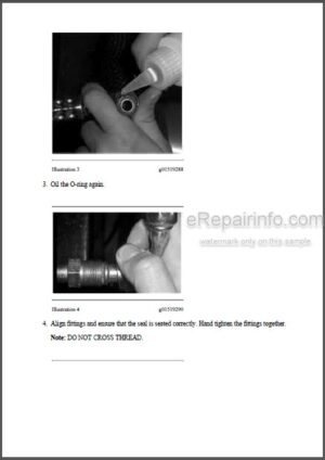
Disconnecting Snap To Connect Fittings
Fuel Priming Pump and Primary Filter (Water Separator) – Remove and Install
Fuel Filter Base – Remove and Install
Governor – Disassemble
Governor – Assemble
Fuel Injection Lines
Fuel Injection Lines – Remove and Install
Fuel Injection Pump
Fuel Injection Nozzles
Fuel Injection Pump
Fuel Injection Nozzles
Fuel Injection Nozzles – Remove
Fuel Injection Nozzles – Install
Fuel Injection Pump – Remove
Fuel Injection Pump – Install
Fuel Injection Pump – Remove and Install
Fuel Injector – Remove and Install
Fuel Injector – Remove and Install
Fuel Priming Pump and Primary Filter (Water Separator) – Remove and Install
Fuel Transfer Pump
Fuel Transfer Pump
Fuel Transfer Pump – Remove
Fuel Transfer Pump – Install
Fuel Transfer Pump – Remove and Install – Mechanical Fuel Transfer Pump
Fuel Transfer Pump – Remove and Install – Electrical Fuel Transfer Pump
Fuel Priming Pump and Primary Filter (Water Separator) – Remove and Install
Fuel Shutoff Solenoid
Fuel Shutoff Solenoid
Fuel Shutoff Solenoid – Remove and Install
Fuel Shutoff Solenoid – Remove and Install
-HYDRAULIC SYSTEM
General Information
Pilot Hydraulic System
Pilot Valve (Joystick)
Work Tool Hydraulic System
Control Valve (Work Tool)
Control Manifold and Solenoid (Work Tool Positioner)
General Information
Pilot Hydraulic System
Pilot Valve (Joystick)
Work Tool Hydraulic System
Control Valve (Work Tool)
Control Manifold and Solenoid (Work Tool Positioner)
Machine Preparation
Visual Inspection
Operational Checks
Hydraulic System Troubleshooting
System Pressure – Release
Hydraulic Oil Contamination – Test
Main Relief Valve – Test and Adjust
Line Relief Valve – Test and Adjust A
ccumulator (Pilot) – Test and Charge
Pilot System Pressure – Test
Pump Flow – Test
Worksheets – Troubleshoot
Machine Preparation
Visual Inspection
Operational Checks
Hydraulic System Troubleshooting
System Pressure – Release
Hydraulic Oil Contamination – Test
Main Relief Valve – Test and Adjust
Line Relief Valve – Test and Adjust
Accumulator (Pilot) – Test and Charge
Pilot System Pressure – Test
Pump Flow – Test
Worksheets – Troubleshoot
MID 106 – CID 1939 – FMI 03
MID 106 – CID 1939 – FMI 06
MID 106 – CID 1940 – FMI 03
MID 106 – CID 1940 – FMI 05
MID 106 – CID 1940 – FMI 06
Hydraulic System Pressure – Release
Hydraulic System Pressure – Release
Disconnecting Snap To Connect Fittings
Hydraulic System Pressure – Release
Accumulator – Remove and Install
Radiator and Hydraulic Oil Cooler
Radiator and Hydraulic Oil Cooler (Fan)
Radiator and Hydraulic Oil Cooler
Radiator and Hydraulic Oil Cooler (Fan)
Radiator and Hydraulic Oil Cooler – Remove
Radiator and Hydraulic Oil Cooler – Install
Lift Cylinder
Tilt Cylinder – Right Hand
Tilt Cylinder – Left Hand
Coupler Cylinder
Lift Arm Cylinder and Mounting
Lift Cylinder
Tilt Cylinder – Right Hand
Tilt Cylinder – Left Hand
Coupler Cylinder
Lift Arm Cylinder and Mounting
Coupler Cylinder – Remove and Install
Tilt Cylinder – Remove
Tilt Cylinder – Install
Lift Cylinder – Remove
Lift Cylinder – Install
Return Manifold
Control Manifold and Solenoid (Parking Brakelpdf
Control Manifold and Solenoid (Parking Brake)
Control Manifold (Quick Coupler)
Control Manifold and Solenoid (Parking Brake)
Control Manifold and Solenoid (Parking Brake)
Control Manifold (Quick Coupler)
Radiator and Hydraulic Oil Cooler
Radiator and Hydraulic Oil Cooler (Fan)
Gear Motor (Fan)
Radiator and Hydraulic Oil Cooler
Radiator and Hydraulic Oil Cooler (Fan)
Gear Motor (Fan)
Gear Motor (Fan) – Demand
Gear Motor (Fan) – Remove
Gear Motor (Fan) – Install
Gear Motor – Remove
Gear Motor – Disassemble
Gear Motor – Assemble
Gear Motor – Install
Gear Pump
Piston Pump
Gear Pump
Piston Pump
Gear Pump – Remove
Gear Pump – Disassemble
Gear Pump – Assemble
Gear Pump – Install
Hydraulic Tankpdf
Hydraulic Tank
Hydraulic Tank – Remove
Hydraulic Tank – Install
Control Valve (Work Tool)
Control Valve (Work Tool) – Remove
Control Valve (Work Tool) – Disassemble
Control Valve (Work Tool) – Assemble
Control Valve (Work Tool) – Install
Diverter Valve – Install
Pilot Operated Hydraulic Control
Pilot Operated Hydraulic Control – Hydrostatic
Pilot Operated Hydraulic Control – Remove
Pilot Operated Hydraulic Control – Disassemble
Pilot Operated Hydraulic Control – Assemble
Pilot Operated Hydraulic Control – Install
Solenoid Valve and Mounting (Coupler) – Remove and Install
Control Manifold and Solenoid (Parking Brake)
Control Manifold (Quick Coupler)
Control Manifold and Solenoid (Parking Brake)
Control Manifold and Solenoid (Work Tool Positioner)
Control Manifold (Quick Coupler)
Solenoid Valve (Compressor Motor) – Remove and Install
-IMPLEMENTS
Lift Arms – Remove
Lift Arms – Install
-LUBRICATION SYSTEM
Lubrication System
Engine Crankcase Pressure (Blowby) – Test
Engine Oil Pressure – Test
Engine Oil Pump – Inspect
Excessive Engine Oil Consumption – Inspect
Engine Crankcase Pressure (Blowby) – Test
Engine Oil Pressure – Test
Engine Oil Pump – Inspect
Excessive Engine Oil Consumption – Inspect
Disconnecting Snap To Connect Fittings
Crankcase Breather – Remove and Install
Crankcase Breather – Remove and Install – Naturally Aspirated Engines
Crankcase Breather – Remove and Install – Turbocharged Engines
Engine Oil Filter
Engine Oil Lines
Engine Oil ReliefValve
Engine Oil Line – Remove and Install
Engine Oil Relief Valve – Remove and Install
Engine Oil Line – Remove and Install
Engine Oil Relief Valve – Remove and Install
Engine Oil Pump
Engine Oil Relief Valve
Engine Oil Pump
Engine Oil Relief Valve – Remove and Install
Engine Oil Pump – Remove
Engine Oil Pump – Install
Engine Oil Relief Valve – Remove and Install
Engine Oil Pump – Remove
Engine Oil Pump – Install
Engine Oil Relief Valve
-MACHINE ARRANGEMENT
Heating and Air Conditioning Service Publications
Service Intervals
-OPERATOR STATION
Pilot Valve (Joystick)
Switches
Indicators
Sensors
Switches
Indicators
General Information
Identifying the Refrigerant
Identifying the Air Conditioning System
Identifying the Heating System
Refrigerant Expansion Valve System
Refrigerant Orifice Tube System
Refrigerant Compressor
Refrigerant Condenser
Refrigerant Receiver-Dryer
Refrigerant Expansion Valve
In-line Refrigerant Dryer
Refrigerant Orifice Tube Assembly
Evaporator Coil
Refrigerant Accumulator
Refrigerant Compressor Protection System
Temperature Control
Cab Pressurization and Filtration System
Condensate Drainage System
Service Intervals
Glossary of Terms
Machine Preparation for Testing and Adjusting
Air Conditioning Performance – Test
Refrigerant Leakage – Test
Manifold Gauge Set (Refrigerant) – Install
Refrigerant Recovery
Refrigerant System – Flush
Refrigerant Oil – Test
Refrigerant Compressor – Test
Refrigerant System – Evacuate
Refrigerant System – Charge
Manifold Gauge Set (Refrigerant) – Remove
Compressor Protection System – Test
Electronic Heat Control – Test
Heater Performance – Test
MID 106 – CID 0070 – FMI 04
MID 106 – CID 1187 – FMI 04
MID 106 – CID 1188 – FMI 04
MID 106 – CID 1189 – FMI 00
MID 106 – CID 1189 – FMI 01
MID 106 – CID 1189 – FMI 04
MID 106 – CID 1189 – FMI 08
MID 106 – CID 1190 – FMI 04
MID 106 – CID 1695 – FMI 04
MID 106 – CID 1935 – FMI 03
MID 106 – CID 1935 – FMI 04
Switch (Two Speed)
Switch (Hydraulic Lockout)
Switch (Armrest) and Switch (Seat)
Switch (Parking Brake)
Switch (Interlock Override)
Switch (Continuous Flow)
Armrest Indicator Is Flashing
Parking Brake Indicator Is Flashing
Parking Brake Indicator and Armrest Indicator Are Flashing
Parking Brake Indicator and Armrest Indicator Do Not Function Correctly
Switch (Hydraulic Lockout)
Switch (Parking Brake)
Required Tools
Machine Preparation forTroubleshooting
General Troubleshooting Information
Visual Inspection (Troubleshooting)
Air Conditioning System Troubleshooting
Heating System Troubleshooting
Troubleshooting Heating and Air Conditioning Control System
Troubleshooting Condensate Drainage System
System Capacities for Refrigerant (Paving Products)
Air Conditioner and Heater – Remove
Air Conditioner and Heater – Disassemble
Air Conditioner and Heater – Assemble
Air Conditioner and Heater – Install
Refrigerant Condenser and Mounting – Remove and Install
Refrigerant Accumulator – Remove and Install
Solenoid Valve (Compressor Motor) – Remove and Install
Gear Motor – Remove
Gear Motor – Disassemble
Gear Motor – Assemble
Gear Motor – Install
Refrigerant Compressor and Support Housing – Remove and Install
General Information
Machine Preparation for Disassembly and Assembly
Air Conditioner Lines – Remove and Install
Refrigerant Compressor – Remove and Install
Refrigerant Accumulator – Remove and Install
Refrigerant Expansion Valve – Remove and Install
Refrigerant Receiver-Dryer – Remove and Install
In-Line Refrigerant Dryer – Remove and Install
Refrigerant Orifice Tube Assembly – Remove and Install
Gas Spring Group (Cab)
Gas Spring Group (Cab)
Cab – Tilt
Cab – Remove
Cab – Install
Gas Spring – Remove and Install
Pilot Operated Hydraulic Control
Pilot Operated Hydraulic Control – Hydrostatic
Pilot Operated Hydraulic Control – Remove
Pilot Operated Hydraulic Control – Disassemble
Pilot Operated Hydraulic Control – Assemble
Pilot Operated Hydraulic Control – Install
Pilot Operated Hydraulic Control – Disassemble
Pilot Operated Hydraulic Control – Assemble
Pilot Operated Hydraulic Control – Install
Refrigerant Condenser and Mounting – Remove and Install
Air Conditioner and Heater – Remove
Air Conditioner and Heater – Disassemble
Air Conditioner and Heater – Assemble
Air Conditioner and Heater – Install
Pilot Operated Hydraulic Control – Remove
Pilot Operated Hydraulic Control – Disassemble
Pilot Operated Hydraulic Control – Assemble
Pilot Operated Hydraulic Control – Install
ROPS Mounting
Seat – Remove and Install
Window Wiper Motor – Remove and Install
-POWER TRAIN
Pilot Valve (Joystick)
Hydrostatic System
Piston Pump (Hydrostatic)
Piston Motor (Hydrostatic)
Tandem Drive and Axle
Pilot Valve (Joystick)
Hydrostatic System
Piston Pump (Hydrostatic)
Piston Motor (Hydrostatic)
Tandem Drive and Axle
Machine Preparation
Visual Inspection
Operational Checks
Hydrostatic System Troubleshooting System Pressure – Release
Hydrostatic System – Flush and Fill Hydrostatic System – Test and Adjust Worksheets – Troubleshoot
Machine Preparation
Visual Inspection
Operational Checks
Hydrostatic System Troubleshooting
System Pressure – Release
Hydrostatic System – Flush and Fill
Hydrostatic System – Test and Adjust (2j
Worksheets – Troubleshoot (2j
MID 106 – CID 0598 – FMI 03
MID 106 – CID 0598 – FMI 05
Parking Brake Intermittent
Hydraulic System Pressure – Release
Axle
Axle
Axle – Remove
Axle – Disassemble
Axle – Assemble
Axle – Install
Chain (Drive) Tension – Adjust
Pump Mounting (Hydrostatic)
Tandem Drive
Pump Mounting – Remove and Install
Chain (Drive) – Remove
Chain (Drive) – Install
Hydraulic Oil Filter
Hydraulic Oil Filter
Return Manifold
Return Manifold
Piston Motor
Motor Mounting (Hydrostatic)
Piston Motor
Motor Mounting (Hydrostatic)
Piston Motor (Hydrostatic) – Remove
Piston Motor (Hydrostatic) – Disassemble
Piston Motor (Hydrostatic) – Assemble
Piston Motor (Hydrostatic) – Install
Piston Pump (Hydrostatic) – Remove
Piston Pump (Hydrostatic) – Disassemble
Piston Pump (Hydrostatic) – Assemble
Piston Pump (Hydrostatic) – Install
Pilot Operated Hydraulic Control – Remove
Pilot Operated Hydraulic Control – Disassemble
Pilot Operated Hydraulic Control – Assemble
Pilot Operated Hydraulic Control – Install
Solenoid Valve and Mounting (Parking Brake) – Remove and Install – One Speed
Solenoid Valve and Mounting (Parking Brake) – Remove and Install – Two Speed Tire and Rim
Tire and Rim
Tire and Rim – Remove and Install
-SERVICE EQUIPMENT AND SUPLIES
Cab Pressurization and Filtration System
Manifold Gauge Set (Refrigerant) – Install
Manifold Gauge Set (Refrigerant) – Remove
Heating and Air Conditioning Service Publications
Required Tools
Fuel Priming Pump and Primary Filter (Water Separator) – Remove and Install
-WORK TOOLS
Coupler Cylinder.pdf
Quick Coupler.pdf
Coupler Cylinder .pdf
Quick Coupler – Remove and Install
What you get
You will receive PDF file with high-quality manual on your email immediately after the payment.


Anonymous (verified owner) –
Extremely comprehensive , great value for the price and fast delivery. Will definitely get my repeat business.