


Factory Repair Manual For Caterpillar 313B CR Excavator. Illustrations, instructions, diagrams for step by step remove and install, assembly and disassembly, service, inspection, repair, troubleshooting, tune-ups.
Format: PDF
Language: English
Pages: 2838
Bookmarks: Yes
Searchable: Yes
Wiring Diagrams: Yes
Hydraulic Diagrams: Yes
Model
Caterpillar 313B CR
BAS00001-UP
Contents
-AIR INLET AND EXHAUST SYSTEM
Air Cleaner – Remove and Install
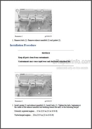
Exhaust Manifold – Remove and Install
Air Inlet Manifold – Remove
Air Inlet Manifold – Install
Turbocharger – Remove
Turbocharger – Install
-BASIC ENGINE
Engine Performance Test – Engine Speed
Engine and Main Hydraulic Pump – Remove
Engine and Main Hydraulic Pump – Install
Cylinder Head – Remove
Cylinder Head – Install
Valve Mechanism Cover – Remove and Install
Rocker Shaft and Push Rod – Remove
Rocker Shaft and Push Rod – Install
-COOLING SYSTEM
Water Temperature Regulator – Remove and Install
Radiator and Hydraulic Oil Cooler – Remove
Radiator and Hydraulic Oil Cooler – Install
-ELECTRICAL AND STARTING SYSTEM
Systems Operation
Testing and Adjusting
Specifications / Disassembly and Assembly
-FRAME AND BODY
Counterweight – Remove and Install
Swing Drive – Remove
Swing Drive – Assemble
Swing Drive – Install
Upper Frame
Undercarriage Frame – Remove
Undercarriage Frame – Install
Swing Gear and Bearing
Swing Gear and Bearing – Remove and Install
Travel Motor Guard
-FUEL SYSTEM
Systems Operation
Testing and Adjusting
Specifications / Disassembly and Assembly
-HYDRAULIC SYSTEM
Systems Operation
Testing and Adjusting
Specifications / Disassembly and Assembly
-IMPLEMENTS
CP Boom – Auxiliary
Boom – 4650 mm (15 feet 3 inch)
Boom – Remove
Boom Bearings and Seals – Remove
Boom Bearings and Seals – Install
Boom – Install
Bucket Linkage
Specifications / Disassembly and Assembly
Bucket Linkage – Remove
Bucket Linkage Bearings and Seals – Remove
Bucket Linkage Bearings and Seals – Install
Bucket Linkage – Install
Stick – Auxiliary 2500 mm (8 feet 2 inch)
Stick – 2500 mm (8 feet 2 inch)
Stick – 3000 mm (9 feet 10 inch)
Stick – Auxiliary 3000 mm (9 feet 10 inch)
Stick – Remove
Stick Bearings and Seals – Remove
Stick Bearings and Seals – Install
Stick – Install
-LUBRICATION SYSTEM
Engine Oil Level Gauge (Dipstick) – Remove and Install
-MACHINE ARRANGEMENT
Heating and Air Conditioning Service Publications
-OPERATOR STATION
Swing Parking Brake
Travel Control – Straight
General Information
Air Conditioning System
Refrigerant Compressor
Refrigerant Condenser
Refrigerant Receiver-Dryer
Pressure Switch (Refrigerant Pressure Cutoff)
Refrigerant Expansion Valve
Evaporator Coil
Blower Motor
Actuator Motor (Water Valve)
Air Conditioning and Heating System Sensor Operation – Thermostatic Switch
Control Panel (Air Conditioner and Heater)
Air Conditioning System Schematic
Heater System (Cab)
Control Panel (Cab Heater)
Heater Core (Cab)
Identifying the Refrigerant
Identifying the Air Conditioning System
Identifying the Heating System
Refrigerant Expansion Valve System
Refrigerant Orifice Tube System
Refrigerant Compressor
Refrigerant Receiver-Dryer
Refrigerant Expansion Valve
In-line Refrigerant Dryer
Refrigerant Orifice Tube Assembly
Evaporator Coil
Refrigerant Accumulator
Refrigerant Compressor Protection System
Temperature Control
Cab Pressurization and Filtration System
Condensate Drainage System
Service Intervals
Glossary of Terms
Wiper Motor Does Not Rotate – Troubleshoot
Wiper Motor Does Not Stop – Troubleshoot
Window Washer Does Not Activate – Troubleshoot
Horn Does Not Sound – Troubleshoot
Radio Does Not Activate – Troubleshoot
Radio Does Not Sound – Troubleshoot
Heater Does Not Activate – Troubleshoot
Circuit for Low Idle Switch – Troubleshoot
Machine Preparation for Troubleshooting
General Troubleshooting Information
Visual Inspection
Air Conditioning System Troubleshooting – Faulty Cooling
Air Conditioning System Troubleshooting – Gauge Pressure
Air Conditioning System Schematic
Heating System Troubleshooting – Faulty Heating
Heating System Schematic
Refrigerant Recovery
Manifold Gauge Set (Refrigerant) – Install
Refrigerant System – Evacuate
Refrigerant System – Flush
Refrigerant Leakage – Test
Refrigerant System – Charge
Manifold Gauge Set (Refrigerant) – Remove
Pressure Switch (Refrigerant Pressure Cutoff) – Test
Control Panel – Test
Speed Control – Test
Belt – Test
Machine Preparation for Testing and Adjusting
Air Conditioning Performance – Test
Refrigerant Leakage – Test
Manifold Gauge Set (Refrigerant) – Install
Refrigerant Recovery
Refrigerant System – Flush
Refrigerant Oil – Test
Refrigerant Compressor – Test
Refrigerant System – Evacuate
Refrigerant System – Charge
Manifold Gauge Set (Refrigerant) – Remove
Compressor Protection System – Test
Electronic Heat Control – Test
Heater Performance – Test
Required Tools
Machine Preparation for Troubleshooting
General Troubleshooting Information
Visual Inspection (Troubleshooting)
Air Conditioning System Troubleshooting
Heating System Troubleshooting
Troubleshooting Heating and Air Conditioning Control System
Troubleshooting Condensate Drainage System
Refrigerant Compressor
Pressure Switch (Refrigerant Pressure Cutoff)
Refrigerant Relief Valve
Air Conditioner Lines
System Capacities for Refrigerant (Excavators) – 304 CR, 305 CR, 313B CR, 321BCR
Refrigerant Receiver-Dryer – Remove and Install
Refrigerant Compressor – Remove and Install
Machine Preparation for Disassembly and Assembly
Air Conditioner Lines – Remove and Install
Refrigerant Accumulator – Remove and Install
Refrigerant Expansion Valve – Remove and Install
Refrigerant Receiver-Dryer – Remove and Install
In-Line Refrigerant Dryer – Remove and Install
Refrigerant Orifice Tube Assembly – Remove and Install Cab – Remove
Cab – Install
Pilot Valve (Travel) – Remove
Pilot Valve (Travel) – Disassemble
Pilot Valve (Travel) – Assemble
Pilot Valve (Travel) – Install
Lines (Heater)
Seat – Remove and Install
-POWER TRAIN
Final Drives and Travel Motors
Duo-Cone Conventional Seals – Install (2)
Final Drive and Travel Motor – Remove
Final Drive and Travel Motor – Disassemble
Final Drive and Travel Motor – Assemble
Final Drive and Travel Motor – Install
Final Drives and Travel Motors (2)
Final Drive Sprocket – Remove and Install
Track Roller – Remove
Track Roller – Disassemble
Track Roller – Assemble
Track Roller – Install
Track – Separate
Track – Connect
Final Drive
Duo-Cone Conventional Seals – Install
-SERVICE EQUIPMENT AND SUPPLIES
Cab Pressurization and Filtration System
Required Tools
Manifold Gauge Set (Refrigerant) – Install
Manifold Gauge Set (Refrigerant) – Remove
Heating and Air Conditioning Service Publications
Required Tools (3)
Hydraulic Tank and Filter
Fuel Filter (Primary) and Fuel Filter Base – Remove and Install
Air Cleaner – Remove and Install
-TORQUE SPECIFICATIONS
English (SAE) Fasteners
Ground Engaging Tool (G.E.T.) Fasteners
Installation of Fittings
Straight Thread O-Ring Fittings
Plugs
O-Ring Face Seal Fittings
Bulkhead Nuts
Flare Fittings
Air Conditioning Fittings
Air Brake Fittings
Tapered Pipe Thread Fittings
Miscellaneous Fittings
Hose Clamps
General Information
Metric (ISO) Fasteners
-UNDERCARRIAGE
Front Idler
Recoil Spring
Front Idler and Recoil Spring – Remove
Front Idler – Disassemble
Front Idler – Assemble
Front Idler and Recoil Spring – Install
Track Carrier Roller
Track Roller (Single Flange)
Track Roller Mounting
Track Carrier Roller – Remove
Track Carrier Roller – Disassemble
Track Carrier Roller – Assemble
Track Carrier Roller – Install
Track Roller – Remove
Track Roller – Disassemble
Track Roller – Assemble
Track Roller – Install
Front Idler and Recoil Spring – Remove
Front Idler and Recoil Spring – Install
Recoil Spring
Recoil Spring – Disassemble
Recoil Spring – Assemble
Track Adjuster – Disassemble
Track Adjuster – Assemble
Track Adjuster – Remove
Track Adjuster – Install
-WORK TOOLS
Blade Lift Cylinder
Blade Mounting
Bucket – 1075 Mm (42 Inch)
Bucket – 925 Mm (36 Inch)
Bucket – 625 Mm (24 Inch)
Bucket – 775 Mm (30 Inch)
Bucket – 1225 Mm (48 Inch)
Bucket – Remove
Bucket – Install
What you get
You will receive PDF file with high-quality manual on your email immediately after the payment.


Reviews
There are no reviews yet.