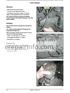
Factory Service Repair Manual For Claas Renault Ares 546 556 566 616 626 636 696 Repair Manual. Tons of illustrations, instructions, diagrams for step by step remove and install, assembly and disassembly, service, inspection, repair, troubleshooting, tune-ups.
Format: PDF
Language: English
Bookmarks: Yes
Searchable: Yes
Wiring Diagrams: Yes
Hydraulic Diagrams: Yes
Model
Claas Renault Ares 546, 556, 566, 616, 626, 636, 696
Contents
-INJECTION DATA SHEETS
-INJECTION FEED TIER I
–IDENTIFICATION
Injection Pumps Identification
–CHARACTERISTICS
Main Characteristics
Engines 4 Cylinders
Engines 6 Cylinders
–TIGHTENING TORQUES
Tightening Torques
–OPERATING PRINCIPLES
Powersupply
Pre-Filter
Fuel Filter
Injection Pump
Injectors
–CHECKS/ADJUSTMENTS
Engine Speed
Checking The Maximum No Load Speed
Checking And Adjusting The Tick-Over
Static Adjustment Of The Injection Pump
Dynamic Adjustment Of The Injection Pump
Injector Adjustment
Cracking Pressure Adjustment
Needle Stroke Adjustment
Shut-Off Solenoid Valve Functional Check
Cold-Start Switch Functional Check
Supply Pressure Check
–REMOVAL/INSTALLATION
Fuel Filter Replacement
Injection System Bleeding
Injection Pump Removal
Injection Pump Installation
Injector Removal
Injector Seating Cleaning (If Required)
Injector Installation
Carrying Over Of The Adjustment Mark Onto The Front Plate
–CONTROL ADJUSTMENTS
Adjusting The Accelerator Cable
–DIAGNOSTIC SHEETS
“Engine Start Up Defect” Sheet
“Irregular Engine Operation” Sheet
“Grey Or Black Smoke Emission” Sheet
“White Smoke Emission’ Sheet
“Check The Fuel Feed Circuit Sheet
–TOOLS
Injection Tools
-ENGINE TIER I
–GENERAL SPECIFICATIONS
Identification Of The Engines
Engines 4 Cylinders
Engines 6 Cylinders
–DIMENSIONAL SPECIFICATIONS
Cylinder Head And Valves
Cylinder Block
Liners And Pistons
Connecting Rods
Crankshaft, Bearings And Flywheel
Camshaft
Distribution
Lubrication
Oil Pump
Cooling
Thermostat
Water Pump And Fan Drive Support
Turbocharger
–TIGHTENING TORQUES
Engine/Transmission Link
Front Chassis / Engine Link
Other Items
–OPERATING PRINCIPLES
Distributor Diagram
Lubrication System
Cooling Circuit
–CHECKS/ADJUSTMENTS
Check Of Engine Oil Pressure
Check Of Compression
Check Of Valve Lift (Engine Cold)
Valve Clearance (Engine Cold)
Valve Adjustment Sequence
Check Of Supercharging Pressure
Check Of The Belt And The Tensioner Spring
–REMOVAL/INSTALLATION
Preliminary Operations
Separate Engine/Front Axle
Separate Engine/Gearbox
Engine Installation Specifications
Cylinder Head
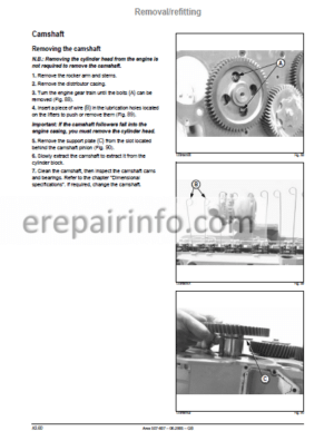
Camshaft
Cylinder Block
Liners
Pistons And Connecting Rods
Crankshaft, Bearings, And Flywheel
Camshaft Balancer Shafts And Distributor
Lubrication
Cooling
Turbocharger
–DIAGNOSTIC SHEETS
“Excessive Oil Consumption” Sheet
Inspection Procedure Of The Cylinder Head Gasket
“Engine Oil Pressure Too High” Sheet
Checking Procedure Of The High Oil Pressure In The Crankcase
“Engine Oil Pressure Too Low Sheet
“Cooling Fluid Temperature Too High* Sheet
“Cooling Fluid Temperature Too Low Sheet
Failure Searching Procedure Of Cylinder Head Seal
–TOOLS
Engine Tools
-INJECTION ADDITIVE TIER II
–TIGHTENING TORQUE
Tightening Torque 4
–OPERATING PRINCIPLES
Injection Pump
Injectors
Situation Of The Different Sensors
–CHECKS/ADJUSTMENTS
Accelerator Control Adjustment
Adjusting The Engine Injector
Supply Pressure Check
Fuel Filter Replacement
–REMOVAL/INSTALLATION
Injection System Bleeding
Injection Pump Removal
Injection Pump Installation
–DIAGNOSTIC SHEETS
Diagnostic Sheets
Spnand Fmi Codes
–TOOLS
Injection Feed Tools Tier Ii
-ENGINE ADDITIVE TIER II
–GENERAL SPECIFICATIONS
Identification Of The Engines
Engines 4 Cylinders
Engines 6 Cylinders
–DIMENSIONAL SPECIFICATIONS
Connecting Rods
–TIGHTENING TORQUES
Front Chassis / Engine Link
Engine/Transmission Link
Crankshaft With Straight Front End
Crankshaft With Tapering Front End
–CHECKS/ADJUSTMENTS
Check Of Supercharging Pressure
Procedure For Checking The Viscous Fan Coupling
–REMOVAL/INSTALLATION
Engine Installation Specifications
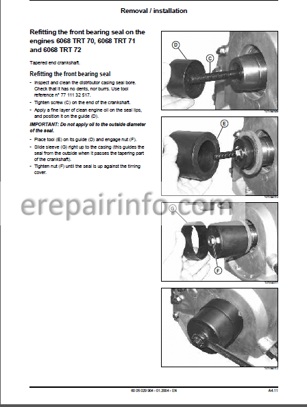
Refitting The Front Bearing Seal On The Engines 6068 Trt 70, 6068 Trt 71 And 6068 Trt 72
–TOOLS
Engine Tool Dps Tier Ii
-GBA 20 GEARBOX
–GENERAL SPECIFICATIONS
Presentation
Gearbox
Revershift Clutch
Quadrishift
Twinshift
Operating Diagram
Gta 2022 – Quadrishift
Gta 2022 – Twinshift
Gta 2023 – Quadrishift
Gta 2023 – Twinshift
Dismantling’assembly Range Summary
–TIGHTENING TORQUES AND PRINCIPAL ADJUSTMENTS
Main Clutch – Forward
Main Clutch – Reverse
Input Unit
Gearbox – Adjustment Values
Coupling Spacer Ring / Gearbox
Coupling Gearbox / Rear Axle
–REVERSHIFT CLUTCH POWERCLUTCH FRONT AND REAR
“Powerclutch” Wet Clutches
Reverser Under Torque(Isc)Clutch Operating Diagram
Forward
Reverse
Neutral
Dismantling Range – Access To Front Clutch
Front Clutch
Front Clutch Removal Replacement And Timing
Front Clutch Dismantling And Reassembly
Installation
Dismantling Range – Access To Rear Clutch
Rear Clutch
Rear Clutch Removal And Replacement
–QUADRISHIFT UNIT
General
Operating Diagram
Quadrishift Inlet Unit Removal Range
Clutch And Rear Brake
Preliminary Operations
Removal Of Housing
Removal And Separation Of The Planet Carrier Unit
Assembling The Planet Carriers
Dismantling The Rear Clutch And The Brake
Removauassembly Of The Bearings And The Unit Outlet Shaft
Clutch And Front Brake
Removal And Refitting The Clutch Housing Cover And The Brake
–TWINSHIFT UNIT
General
Operating Diagram
Twinshift Inlet Unit Removal Range
Removal Of Inlet Unit
Adjusting The Preload P4
Removalrefitting The Shaft And Outlet Pinion
Removal Of The Planet Carrier Unit
Removal Of Hydraulic Cover
Refitting The Planet Carrier
Refitting The Hydraulic Cover
Assembling The Planet Carrier
Refitting The Front Cover
–Primary Shaft
General
Primary Shaft Removal/Refitting Range
Preliminary Operations
Removal
Installation
Refitting The Inlet Unit And Primary Shaft Timing
–Rear Intermediary Shaft
General
Rear Intermediary Shaft Removal/Refitting Range
Removal Of Outlet Shaft
Rear Intermediary Shaft Refitting And Timing
–Front Intermediary Shaft
General
Front Intermediary Shaft Removal’Refitting Range
Preliminary Operations
Removal’ Reatting And Assembly Of The Front Intermediary Shaft
–Right Cover And Forks
Operating Principles
Tightness Torques Of Screws On Cover
Tightness Torques Guide Rods And Forks
Gear Fork Locking Adjustment
Removal Of Right Cover
Dismantling The Cover
Installation
Adjusting The Range Fork And Cam Follower
Refitting The Cover
Adjusting The Gear Control Cables
–CRAWLER SPEEDS
General
Operation
Overall View
Removal Of Housing And Crown Wheel
Exploded View
Dismantling The Planet Carrier
Refitting The Planet Carrier And Replacng The Housing
Final Steps
Setting The Controls
–TOOLS
Gearbox Tools
-LOW PRESSURE HYDRAULIC CIRCUIT
–PRESENTATION
Open Centre Circuit
Closed Centrer Circuit
Low Pressure Open Centre Hydraulic Circuit (Fed By The Orbitrol Steering Unit Return)
Low Pressure Closed Centre Hydraulic Circuitlow Pressure Open Centre Hydraulic Circuit
(Fed By The Safety Unit)
–GEARBOX CONTROL AND LUBRICATION
Distribution Valve
Ares 500
Ares 600
Control
Lubrication
–MEASUREMENT AND CHECKING POINTS
Revershift Hydraulic Unit
“Control Values Statement” Sheet
Quadrishift Hydraulic Unit
“Control Values Statement” Sheet
Twinshift Hydraulic Unit
“Control Values Statement” Sheet
Open Centre Hydraulic Circuit Ares 500-600 (Check Valid For Closed Centre Circuit Unless Otherwise Indicated)
“Control Values Statement’ Sheet
–REAR AXLE CONTROL AND LUBRICATION
Open Centre Circuit
Closed Centre Circuit
–MEASUREMENT AND CHECKING POINTS
Lubrication Circuit
Control And Lubrication Circuit
Open Centre: Ares 500-600 Tractors
“Control Values Statement’ Sheet
Open Centre: Tractors Ares 600 With Braking Booster
“Control Values Statement’ Sheet
Closed Centre: Ares 500 Tractors
“Control Values Statement’ Sheet
Closed Centre: Tractors Ares 600 With Braking Booster
–TOOLS
Low Pressure Hydraulic Circuit Tools
-GEARBOX ADDITIVE TIER II
–GENERAL SPECIFICATIONS
Presentation
Quadrishift Overdrive Operating Diagram
–REAR INTERMEDIARY SHAFT
Rear Intermediary Shaft Timing
Final Fitting Of The Rear Intermediary Shaft
-LOW PRESSURE HYDRAULIC CIRCUIT ADDITIVE TIER II
–PRESENTATION
Closed Centre Circuit Depth Of Entry Ls 100 B’min
Low Pressure Closed Centre Hydraulic Circuit Ls 100 B’min
Distribution Valve
–LUBRICATION LS 100 L/MIN CIRCUIT
Gearbox And Power Take-Off
Brakes
–MEASUREMENT AND CHECKING POINTS
Checking The Flow Coming From The Steering Box
Checking The Control Pressure
Checking The Cooler Bypass
Checking The Lubrication Pressure
–“CONTROL VALUES STATEMENT” SHEET
“Control Values Statement” Sheet
–TOOLS
Low Pressure Hydraulic Circuit Tools
-REAR AXLE
–PRESENTATION
Technical Specifications
Rear Transmission Unit (Cross Section)
Central Housing Unit (Lengthwide Section)
–SHD HEAVY DUTY AXLE TUBES
Overall And Exploded View
Axle Tube Assembly
Planet Carrier
Bearingsand Seals
Preload Of The Axle Shaft Bearings (P1)
Replacing The Wheel Stud
–SHD HEAVY DUTY AXLE TUBES
Overall And Exploded View
Axle Tube Assembly
Planet Carrier
Bearingsand Seals
Preload Of The Axle Shaft Bearings (P1)
Replacing The Wheel Stud
–DIFFERENTIAL
Overall And Exploded View
Disassembly And Reassembly Of The Differential Lock
Differential Removal
Disassembling The Differential And The Crown Wheel
Removal And Disassembly Of The Drive Pinion
Adjustment Of The Pinion Protusion Distance (P3)
Preload Adjustment Of The Drive Pinion Bearings (P1)
Preload Adjustment Of The Bearings Of The Differential Bearing Blocks (P2)
Backlash Adjustment (J2)
Reassembly Of The Crown Wheel And Differential
Reassembly And Installation Of The Drive Pinion
–REAR POWER TAKE-OFF
Technical Specifications
Overall View
–REAR POWER TAKE OFF CLUTCH
Overall And Exploded View
Removal/Refitting The Power Take-Off Clutch
Clutch Dissassembly And Reassembly
–UPPER SHAFT REAR POWER TAKE-OFF
Exploded View
2 Speed Power Take-Off Upper Shaft (Without Adjustment)
2 Speed Power Take-Off Upper Shaft (With Adjustment)
4 Economical Speed Power Take-Off Upper Shaft (Without Adjustment)
4 Economical Speed Power Take-Off (With Adjustment)
Economy Power Take-Off Controls
–LOWER SHAFT REAR POWER TAKE-OFF
Overall And Exploded View
Removal-Installation Of The Stub Shaft
Removal-Installation Of The Rear Bearing
Disassembly And Reassembly Of The 540 And 1Cc0 Rpm Pinionsand Of The Front Bearing
–PROPORTIONAL POWER TAKE-OFF
Overall And Exploded View
Power Take-Off Disassembly
Power Take-Off Reassembly
Assembly And Adjustment Of The Control Cable
Detail Of The Proportional Pto Control
–TOOLS
Rear Axle Tools And Rear Power Take-Off
-SERVICE BRAKES – HAND BRAKE
–PRESENTATION
Characteristics
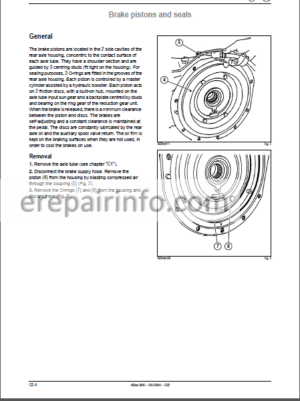
–BRAKE PISTONS AND SEALS
Draining The Operating Brake Circuit
Service Brake
–TRACTORS NOT EQUIPPED WITH BOOSTERS
Presentation
Assembling The Master Cylinders
–TRACTORS EQUIPPED WITH BOOSTERS AND BRAKING VALVE
Open Centre Hydraulic Circuit
Closed Centre Hydraulic Circuit (Ls 110 Iain)
Closed Centre Hydraulic Circuit (Ls 100 Lain)
–TRACTORS FITTED WITH BOOSTERS LUCAS
Master Cylin Der/Booster Exchange And Adjustment
–TRACTORS FITTED WITH BOOSTERS IRUNA
Description Of Master Cylinders-Boosters Iruna
–ADJUSTMENT OF THE BRAKE PEDALS
Adjustment Procedure
–BLEEDING THE BRAKING CIRCUIT
Initial Checks
Manual Bleeding Of The Service Brake Circuit
Bleeding The Braking Circuit (With Drain Cock)
Checking The Effectiveness Of The Air Bleed
–HAND BRAKE
Presentation
Removal / Installation
Hand Brake Adjustment
–TOOLS
Service Brake And Hand Brake Tools
-4 WD POWER TAKE-OFF HOUSING
–PRESENTATION
Technical Specifications
–REMOVAL/INSTALLATION
Overall And Exploded View
Clutch Assembly Removal
Clutch Disassembly
Clutch Reassembly
Clutch Assembly Installation
–TOOLS
4 Wd Power Take-Off Housing Tools
-REAR AXLE ADDITIVE TIER II
–GENERAL SPECIFICATIONS
Rear Axle
Hd+ Gpa 22+ Heavy Duty Axle Tubes
–PROPORTIONAL POWER TAKE-OFF
Presentation
Removal / Refitting The Housing
Setting The Controls
Switch Operation
-STANDARD FRONT AXLE
–PRESENTATION
General Specifications
Differential And Bevel Gear
Epicycloid Reducer And Universal Drive Shaft
Torque Loadings And Settings
Use Of Special Tooling
Geographical Situation Of Control Elements
Operating Diagram
Maintenance
–REMOVAL/INSTALLATION
Preliminary Operations
Adjusting The Wheel Alignment
Steering Links Ano Actuator
Epicycloid Reducers And Wheel Hubs
Wheel Pins – Universal Drive Shafts
Axle Body
Crown Wheel-Bevel Gear And Differential – Axle A 86-1
Crown Wheel-Bevel Gear And Differential – Axle A 87-2
Crown Wheel-Bevel Gear And Differential – Axle A 88-3
Setting The Final Drive
Adjustment Of The Pinion Protrusion
Setting The Final Drive Pre-Load
Adjustment Of The Meshing Backlash
Differential Bearing Block Pre-Load
Anal Reassembly
–HYDRAULIC CHECKS
“Control Values Statement’ Sheet
Pressure Intake On The A 88-3 Axle Differential Locking Circuit
–ELECTRIC CHECKS
Wiring On Drivetronic Iii
–TOOLS
Standard Front Axle Tools
-PROACTIV FRONT AXLE
–PRESENTATION
General Specifications
Torque Loadings And Settings
Layout Of Items
Operation
Differential Locking
Front Axle Engagement
Suspension
Operating Diagram
Maintenance
–REMOVAL/INSTALLATION
Preliminary Operations
Adjusting The Wheel Alignment
Steering Links Ano Actuator
Epicycloid Reducers And Wheel Hubs
Epicycloid Reducer
Wheel Hub
Wheel Swivel Pinsand Upper Arm
Wheel Swivel Pin
Upper Arm
Suspension Cylinder And Lower Arm
Wheel Pivots
Lower Arm And Torsion Bar
Setting The Torsion Bar Pre-Loads
Universal Joint Shafts
Bevel Gear And Differential
Adjustment Of The Pinion Protrusion
Setting The Final Drive Pre-Load
Adjustment Of The Meshing Backlash
Differential Bearing Block Pre-Load
Installation
Suspension Position Sensor
–HYDRAULIC CHECKS
Check Group
Accumulator Inflation
“Control Values Statement Sheet
Pressure Intake On The Differential Locking Circuit
Pressure Intake At The Level Of The Suspension Cylinders
Pressure Intake Of The “Ls” Signal
–ELECTRIC CHECKS
Control Switches
Suspension Control Solenoids
Suspension Sensors
Calibrating The Suspension
Wiring On Drivetronic Iii
BREAKDOWN DIAGNOSIS
Values To Be Checked
Interpreting Error Cooes
–TOOLS
Proactiv Front Axle Tools
-OPEN CENTRE HYDRAULICS
–PRESENTATION
Characteristics
Hydraulic Circuit
Hydraulic Circuit – Layout Of Items
Tightness Torques Of Hydraulic Components And Connections
–REMOVAL/REFITTING OF ELEMENTS
Rh Cover
High Pressure Valve
Hydraulic Pump
Braking Valve
Supply Plate And Distributors
Supply Plate
Lifting Distributor
Auxiliary Distributor 3 Positions
Control Adjustments
Lifting Jacks
Steering Unit
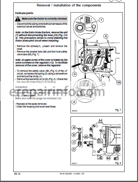
Access To Steering Unit
Lift Cover
–MEASUREMENT AND CHECKING POINTS
“Control Values Statement” Sheet
Lifting
Steering Actuator
Steering Unit
–STEERING DIAGNOSIS
Difficult Steering Wheel Manoeuvres
Abnormal Steering Wheel Vibrations – “Shimmy” (Oscillations) In Steering -Inaccurate Steering – Shim Clearance Take-Up
–TOOLS
Hydraulic Tools
-CLOSED CENTRE HYDRAULICS (110 L/MIN)
–PRESENTATION
Characteristics
Hydraulic Circuit
Hydraulic Circuit – Layout Of Items
Tightness Torques Of Hydraulic Components And Connections
–REMOVAL/REFITTING OF ELEMENTS
Rh Cover
Variable Capacity Pump
Priority Units (No Trailor Brake)
Priority Units (With Trailor Brake)
Lh Cover
Booster Pump
Replacement Of Pump Seals
Supply Plate And Distributors
Supply Plate
Auxiliary Distributor 3 Positions ‘zf’ Option ‘ko*
Auxiliary Distributor 4 Positions “Ko – Zf*
Auxiliary Distributor With Electrohydraulic Controls
Closing Plate
Control Adjustments
–MEASUREMENT AND CHECKING POINTS
Power Take-Offs
Variable Capacity Pump Supercharge Pressure
Idling Pressure And Xls Pressure
Flow And Maximum Pressure
Checking The Auxiliary Distributors Flow Regulator
Auxiliary Distributor With Automatic Return To Neutral
Lifting
Steering
“Control Values Statement” Sheet
–TOOLS
Hydraulic Tools
-CLOSED CENTRE HYDRAULICS (100 L/MIN)
–PRESENTATION
Characteristics
Tightness Torques Of Hydraulic Connections
General Hydraulic Circuit Closed Centre Ls 100 L’min
Lh Hydraulic Cover
Rh Hydraulic Cover (With Braking Valve)
Geographical Situation Of The Hydraulic Components On The Priority Unit
–REMOVAL/REFITTING OF ELEMENTS
Removal’Refitting The Rh Cover
Removal’Refitting The Main Pump
Replacing The Rh Cover
Adjusting The Sensor
Removal’Refitting The Lh Cover
Removal’Refitting The Steering Pump
Table Of The Other Elements Common To The Hydraulic Circuits Closed Centre 110 L’min And Open Centre
–STEERING MEASUREMENT AND CHECKING POINTS
Checking The Steering Pump
Checking The Steering Gear Box And Actuator
–STEERING “CONTROL VALUES STATEMENT” SHEET
Steering “control Values Statement” Sheet
–HYDRAULIC MEASUREMENT AND CHECKING POINTS
Checking The Idling Pressure Of The 14 CM3 Pump
Checking Pressures For A Flow Less Than 40 L/Min And A Flow Of 60 Lmin
Checking The Minimummaximum Flow Of The Auxiliary Distributors
Checking The Braking Valve
–HYDRAULIC “CONTROL VALUES STATEMENT” SHEET
Hydraulic ’Control Values Statement Sheet
–TOOLS
High Pressure And Steering Hydraulic Circuit Tools
-ELECTRICITY
–GENERAL CONTENTS
Item List
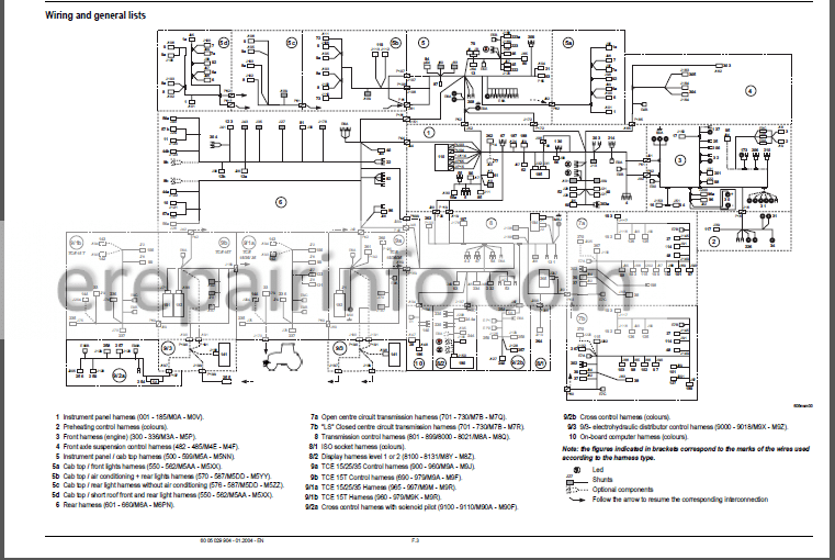
Wiring And General Lists
Schematic Diagrams According To Functions
Connector And Harness Tracking
–TOOLS
Electricity Tools
-INSTRUMENT PANEL
–GENERAL
Description Of Panel
Allocation Of Light Bulbs To Warning Lights
Indicator Operation
Temperature Display And Diesel Gauge
Alarm Lights (Red)
–METADIAG BREAKDOWN DIAGNOSIS
Removal/Refitting Connectors “Jx1” And “Jx2”
Connection And Functions Of The Wires Of The Double Connector “jx2”
Connection And Functions Of The Wires Of The Single Connector “Jx1”
Metadiag Connection For Instrument Panel Application
Calibration On 100 Metres
Low Pressure Oil Pressure Sensor
Engine Oil Pressure Sensor
Oil Temperature Sensor
Speed Sensor
–TOOLS
Instrument Panel Tools
-ELECTRONIC/RADAR LIFT
–PRESENTATION
Simplified Version: Tce 15
Simplified Version: Tce 25
Access To The Installed Software Version (Tce 15 Tce 25)
Linkage Operation Conditions
Version Tce 15 T
Linkage Operation Conditions
–CHECKS AND ADJUSTMENTS
Position And Speed Sensors
Connections On Units Tce 15/Tce 25
Connections On Units Tce 15 T
Stress Sensor
Position Sensor
Theoretical Speed Sensor
–METADIAG BREAKDOWN DIAGNOSIS APPLICATION TCE 15 T/TCE 15-25
Metadiag Connection For Application Tce 15 T
Inspections
Metadiag Connection For Application Tce 15Tce 25
Inspections
Metadiag Use
–TOOLS
Electronic Lift Tool
-DRIVETRONIC III
–PRESENTATION
Functioning Mode
Geographical Situation Of Controls
Geographical Situation Of Sensors And Solenoids Open Centre Circuit
Geographical Situation Of Sensors Solenoids And Switches
Closed Centre Circuit
Block Diagram Of The Uce
Functions Of The Black Switch (Inputs)
Functions Of The Red Switch (Outputs)
–ELECTRICAL COMPONENTS
Features/Settings
Adjusting The Pedal Position And Stroke
Calibrating The Revershift Clutches
Potentiometer
Inverter Lever
Clutch Control Cycle
Revershift Solenoids (Evp1 And Evp2)
Twinshift And Quadrishift Ii Control Switches
Quadrishift Solenoids (Evi And Ev2)
Electrohydraulic Range Change
Quadrishift Ii Automatic System Control Switch
Quadractiv Control Switch
Accelerator Pedal Angle Detector
Sensors
Transmission Display (Twinshift / Quadrishift Iii Quadractiv)
–FUNCTIONS
Front Axle
Front Axle Electronic Management Modes
Rear Axle
Rear Axle Electronic Management Modes
Wet Clutch
Twinshiftquadrishift Ii
Quadrishift Ii Automatic System Controls
Quadrishift Ilquadract1V Transmission Electronic Management Modes
Twlnshiftiquadrishift Il’quadracttv Transmission Electronic Management Modes Rear Power Take-Off
Rear Power Take-Off Electronic Management Modes
Electronic Power Take-Off Control
Starter Safety Device
–METADIAG DIAGNOSIS
Metadiag Connection
Metadiag Launch
Metadiag Use
Transmission Block Diagram
Uce States
Error Codes
Electrical Tests: Supply And Safety
Electrical Tests: Front Axle
Electrical Tests: Rear Power Take-Off
Electrical Tests: Revershift
Electrical Tests: Quadractiv
Electrical Tests: Ranges
Electrical Tests: Differential Locking
Electrical Tests: Quadrishift
Electrical Tests: Twinshift
–TOOLS
Drivetronic Tools
-INFOTRAC AND ISO SOCKET
–PRESENTATION
Functions Of The On-Board Computer
Description Of The Front Panel
Operation
REMOVAL /INSTALLATION ELECTRIC CHECKS
Removal Of Housing – Changing Bulbs
Iso Socket
Iso Unit
Outside Temperature Probe
Schematic Diagram
Functions Of Connector Wires
Electrical Check Of The Iso Socket
Outside Air Temperature Sensor
Calibrating The Forward Speed
-ELECTROPILOT
–PRESENTATION
Control Description
Connections To The Joystick
Switch Connections
Connections On Unit
Electrohydraulic Distributor
Control Handle Fitting (Joystick)
Electric Checks
–METADIAG BREAKDOWN DIAGNOSIS
Metadiag Connection
Metadiag Use
–TOOLS
Electropilot Tools
-DRIVETRONIC III TIER II ADDITIVE
–LOCATION OF COMPONENTS AND SENSORS
Closed Centre Circuit 100 Litres
–SCHEMATIC DIAGRAM
Electrohydraulic Range Change
Drivetronic
–ADJUSTMENTS
Toc Boc Switches And Angle Detector
Accelerator Pedal Angle Detector
Static Calibration Of Clutches
–METADIAG APPLICATION
Ares Drivetronic 3 Application
Transmission Block Diagram
Electrical Tests
–CONDITIONS FOR PLACING THE TRACTOR IN GRADUATED MODE
Defect On The Tractor’S Forward Speed Sensor
Defect On At Least One Quadrishift Control Solenoid
Can Defect
-ENGINE MANAGEMENT TIER II
–ENGINE MANAGEMENT
Location Of Components And Sensors
Features Of Components And Connections
Adjusting The Accelerator Detector
Metadiag Application
Spnand Fmi Codes
–TOOLS
Engine Management Tools
-LIFT AND FRONT POWER TAKE-OFF
–FRONT LIFT
Characteristics
Exploded View
Tightening Torques
–MEASUREMENT AND CHECKING POINTS
Checking The Jack Pressure
–“CONTROL VALUES STATEMENT” SHEET
Checking The Jack Pressure
–FRONT POWER TAKE-OFF
Characteristics
Exploded View Of The Unit
Removal / Refitting Of The Unit
Clutch Disassembly
Exploded View Of The Housing
–MEASUREMENT AND CHECKING POINTS
Checking The Clutch Feed Pressure
–“CONTROL VALUES STATEMENT” SHEET
Checking The Clutch Feed Pressure
What you get
You will receive PDF file with high-quality manual on your email immediately after the payment.

Anonymous (verified owner) –
Good content
Anonymous (verified owner) –
Good manual.