


Factory Service Repair Manual For Claas Renault Ares 547 557 567 577 617 657 697 Tractors. Tons of illustrations, instructions, diagrams for step by step remove and install, assembly and disassembly, service, inspection, repair, troubleshooting, tune-ups.
Format: PDF
Language: English
Bookmarks: Yes
Searchable: Yes
Wiring Diagrams: Yes
Hydraulic Diagrams: Yes
Model
Claas Renault Ares 547, 557, 567, 577, 617, 657, 697
Contents
-INJECTION SHEET CHECKING PROCEDURE
–CHECKING PROCEDURE
List Of Checking Operations
–MEASUREMENT AND CHECKING POINTS
Checking Operations
Record Of Inspection Results
–APPENDIX
Checking The Hydraulic Pressure
Injection Data Sheets
-DE 10 INJECTION
–DESCRIPTION
Changes To Standards
Description Of The Pump
Complete System
Fuel Filters
Injection Cycle
Injection Order
Injector
Control Of Advance Angle
Engine Computer
Engine Computer Inputs And Outputs
Sensors
Temperature Sensors
–DESCRIPTION AND OPERATION
Pre-Heating Automation
Start-Up Automation
Idle Auto Mation
Water Temperature Degraded Mode
Fuel Temperature Degraded Mode
Air Temperature Degraded Mode
Error Codes
–ADDITIONAL TECHNICAL DETAILS
Transfer Pump
Transfer Pressure Regulator
Transfer Pressure
Internal Pressure Regulator
Fuel Booster System
Discharge And Charge Accumulator
High-Pressure Circuit
–TIGHTENING TORQUES
Tightening Torques
–FILTER ELEMENT
Strainer
Fuel Filters
–INJECTOR PUMP
Removal
Refitting
–INJECTOR
Removal
Adjustment
Refitting
Electronic Control
Schematic Diagram
–ELECTRONIC CONTROL
Schematic Diagram
–MANIFOLD AIR TEMPERATURE SENSOR
Measurement And Checking Points
–ENGINE COOLANT TEMPERATURE SENSOR
Measurement And Checking Points
–FUEL TEMPERATURE SENSOR
Measurement And Checking Points
–CRANKSHAFT POSITION SENSOR
Measurement And Checking Points
–PUMP CONTROL SOLENOID
Measurement And Checking Points
–ACCELERATOR DETECTOR
Measurement And Checking Points
Adjustment
Diagnostic Harness
-ENGINE TIER II
–GENERAL DESCRIPTION
Identification Plate
–TECHNOLOGY OF NON-MOVING PARTS
Engine Block
Wet Liner
Cylinder Head
Valves
–TECHNOLOGY OF MOVING PARTS
Thrust Bearings
Crankshaft
Pistons
Connecting Rods
Rings
Accessory Gear Train
Balance Shaft
“Damper”
–LUBRICATION
Lubrication System
Oil System Components
–COOLING
Cooling System
Components Of Cooling System
–AIR
Air Circulation
Pre-Heating
Dust Rebreathing
–TIGHTENING TORQUES
Front Chassis/ Engine Link
Enginetransmission Link
Crankshaft With Tapering Front End
–DIMENSIONAL SPECIFICATIONS
Cylinder Head And Valves
Cylinder Block
Liners And Pistons
Crankshaft Bearings And Flywheel
Camshaft
Accessory Gear Train
Lubrication
Cooling
Turbocharger
–CHECK
Compression
Engine Oil Pressure
Checking The Turbocharger Pressure
Oil Consumption
Oil Overpressure In Crankcase
Turbocharger
Thermostat
Pistons Protruding
Sleeves Protruding
Valve Lift (Engine Cold)
Adjusting The Valve Rockers (Engine Cold)
Adjustment
Timing Belt
Belt Tensioner
Fan Spider Hub
Fan Drive Shaft
Air Intake Sealing
–REMOVAl/REFITTING
Preliminary Operations
Separate Enginbfront Axle
Separate Enginbgearbox
Particularities On Refitting The Enginbfront Axle
Cylinder Head
Camshaft
Camshaft Bushes
Liners
Pistons And Connecting Rods
Piston Heads And Skirts
Crankshaft Bearings And Flywheel
Vibration Damper And Its Pulley
Flywheel
Changing The Flywheel Ring Gear
Changing The Rear Bearing Seal
Changing The Front Bearing Seal
The Distributor Casing
Mandrels And Timing
Removing The Front Plate
Crankshaft Timing Wheel
Crankshaft Pinion
Changing The Pinion Pins
Reassembly Of The Front Plate
Reassembly Of The Balancer Shafts
Assembling The Upper Distributor
Assembling The Lower Distribution
Fitting The Distributor Casing
Oil Cooler
Oil Sump
Disassembly Of The Oil Pump
Reassembling The Oil Pump
Water Pump
Thermostat
“Engine Oil Pressure Too Low” Sheet
“Engine Oil Pressure Too High” Sheet
“Excessive Oil Consumption” Sheet
“Coolant Temperature Too High” Sheet
Coolant In The Oil Or Vice Versa
-GEARBOX
–MECHANICAL PART
—GENERAL DESCRIPTION
General Description
—“HEXASHIFT” MODULE
Description
Speed Increaser Gearing
Speed Increaser Gearing R = 1
Speed Increaser Gearing R = 1,4
Module 4 Ps
Module 4 Ps R = 058
Module 4 Ps R = 069
Module 4 Ps R = 083
Module 4 Ps R = 1
Module Summary 6 Ps
—REVERTER MODULE UNDER TORQUE
Description
Forward
Reverse
–ROBOT-DRIVEN RANGES MODULE
Description
Kinematics Range ‘aw’
Kinematics Range ’B’
Kinematics Range ‘c’
Kinematics Range ‘d’
Synchronizer Movement
Description Of The Range Jacks
Monitoring Of Synchronizer Position
Summary Of Robot-Driven Ranges Module
—CRAWLER RANGES MODULES
Description
Slow Version R = 1
Slow Version R = 025
Extra Slow Version R = 1
Extra Slow Version R = 007
—CHARACTERISTICS GBA 25
Characteristics Gba 25
—KINEMATICS GBA 25
Kinematics Gba 25
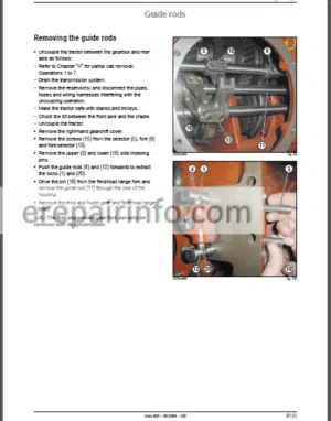
—REMOVAL PROCEDURE
Removal Procedure
—MAIN ADJUSTMENTS
Main Adjustments
—TIGHTENING TORQUES AND SEALANTS
Enginethexashift” Module Coupling
“Hexashift’ Module’range Module Coupling
Range Module’rear Axle Coupling
—“HEXASHIFT” MODULE
Exploded View
Removal {Stage 1 Page 37)
Removal
Refitting
Refitting
—Reverter Module Under Torque
Exploded View
Removal {Stage 2 Page 37)
Removal
Refitting
Refitting
—ROBOT-DRIVEN RANGES MODULE
Exploded View
Removal
Adjusting The Shafts In The Housing
Refitting
—SLOW RANGE
Exploded View
Removing/Refitting The Housing
Removing Adjusting And Refitting The Control System
Setting The Controls
—EXTRA SLOW RANGE
Exploded View
Removing/Refitting The Housing
Removing Adjusting And Refitting The Control System
Setting The Controls
–HYDRAULIC PART
—LOW PRESSURE CIRCUIT 20 BAR
Description
The Valve 20 On 60 L’min And 100 L’min Circuit
20 Bar Vavle On 110 L’min Circuit
Description
“Hexashift” Driving Logic
Reverter Driving Logic Under Torque
Driving Logic Of Robot-Driven Ranges
Description Of The “Hexashift/Reverter Block
Description Of Robot-Driven Ranges
—LOW PRESSURE LUBRICATION CIRCUIT
Description
Lubrication For 60 L’Min And 100 L’min Circuit
Lubrication With 110 Umin Circuit
Lubrication Gba 25
“Hexashift* Lubrication And Reverse Clutch
Lubrication Of Range Upper Shaft And Forward Clutch
Lubrication Of Range Lower Shaft And Reverse Countershaft
—CHARACTERISTICS OF LOW PRESSURE CIRCUITS
60 L’Min Circuit
100 Lmin Circuit
110 Lmin Circuit
—OPEN CENTER GO L/MIN
Hydraulic Diagram
Component Layout
Pressure Restrictors
Lubrication
—“LOAD SENSING” 100 L/MIN
Hydraulic Diagram
Component Layout
Pressure Restrictors
Lubrication
—“LOAD SENSING” 110 L/MIN
Hydraulic Diagram
Component Layout
Distribution Valve
Lubrication
—CONTROL CIRCUIT TIGHTENING TORQUES
Control Circuit Tightening Torques
—SOLENOID VALVE MEASUREMENT AND CHECKING POINTS
Electrical Tests On The Solenoids
—CONTROL UNIT GBA 25 MEASURING AND CHECKING POINTS
Checking The Distribution Unit And Range Solenoid Valve Feed Pressure
Checking The ‘revershiff Feed Pressures
Checking The ’Hexashift” Module Feed Pressures
—GBA 25 “HYDRAULIC INSPECTION RESULTS” SHEET
Gba 25 ‘hydraulic Inspection Results’ Sheet
—GO L/MIN OPEN CENTRE MEASUREMENT AND CHECKING POINTS
Checking The Flow Coming From The Steering Box
Checking The Control Pressure
Cooler Inlet Flow Rate Check
Cooler Inlet Presssure Check
Checking The Lubrication Flow Rate From The Spool Valves And The 10 Cm’ Pump
Lubrication Pressure Check
Lubrication Flow Rates At Diffrent Points Of The Circuit
—60 L/MIN OPEN CENTRE “INSPECTION RESULTS” SHEET
60 Bmin Open Centre “Inspection Results” Sheet
—“LOAD SENSING” 100 L/MIN MEASURING AND CHECKING POINTS
Checking The Flow Coming From The Steering Box
Checking The Control Pressure
Cooler Inlet Flow Rate Check
Cooler Inlet Presssure Check
Checking The Lubrication Flow Rate From The Spool Valves And The 10 Cm’ Pump
Lubrication Pressure Check
Lubrication Flow Rates At Diffrent Points Of The Circuit
—“LOAD SENSING” 100 L/MIN “INSPECTION RESULTS” SHEET
“Load Sensing” 100 Bmin “Inspection Results’ Sheet
—“LOAD SENSING” 110 L/MIN MEASURING AND CHECKING POINTS
Checking The Control Pressure
Lubricating Oil Flow Rate Through The Cooler At 2 000 Rpm
Lubrication I Boost Pressure Check
Lubrication Flow Rates At Diffrent Points Of The Circuit
—“LOAD SENSING” 110 L/MIN “INSPECTION RESULTS” SHEET
“Load Sensing’ 110 Bmin “Inspection Results” Sheet
–ELECTRONIC PART
Electronic Transmission Control
General Description
Presentation ’Auto 5’
Input&’outputs “Auto 55Г
Input&’outputs “Auto 552”
Input&’outputs “Auto 553”
Communication Network
Gears And Safety
Functional Logic
—ELECTRONIC MANAGEMENT OF THE GEARBOX
Powersupplies
Hexashift
Robot-Driven Range
Functional Logic: Example Of Configurations
Reverser Under Torque
Modes Management
“Overdrive”
Functional Logic
Slow Range
Display
—COMPONENT LAYOUT
Component Layout
—ELECTRICAL TESTS
Supply Circuit Switch
Earthing Switch
Manipulator
Contact Sensor
Temperature Sensor (Thermistor)
Variable Reluctance Induction Sensor
Hall-Effect Sensor
Flexible Blade Sensor
“Auto-5* Electronic Unit
Proportional Solenoid Valve
On-‘off Solenoid Valve
—ADJUSTMENTS AND CALIBRATION
Clutch Pedal (“Boc Switch And Position Sensor)
Static Calibration Of Clutches
Modification Of Forward/Reverse Progressivity
—“SPEED AND SAFETY” MEASUREMENT AND CHECKING POINTS
Checking The Low Pressure Switch (118)
Checking The Boost Pressure Switch On The 110 L/Min ‘load Sensing’ Circuit (127)
Checking Engine Speed Theoretical Speed And Reverser Output
Speed Sensors (38) (37) (27)
Checking The Transmission Temperature Sensor (114)
—“SUPPLY” MEASUREMENT AND CHECKING POINTS
Checking The Unit Supply Voltages
—“HEXASHIFT” MEASUREMENT AND CHECKING POINTS
Checking The Upshift And Downshift Switches (63 – 220A) (63 – 2206)
Checking The ‘hexashift’ Proportional Solenoid Valves (271/272273)
—“ROBOT-DRIVEN RANGE” MEASUREMENT AND CHECKING POINTS
Checking The Gear Upshift Gear Downshift And Shift Switches (63 – 22Oa) (63 – 220B) (63)
Checking The Range Change Contact Sensors (278 – 279 – 280 – 28)
Checking The Range Solenoid Valves (274 – 275 – 276 – 277)
—“SHUTTLE REVERSER” MEASUREMENT AND CHECKING POINTS
Checking The Transmission Temperature Sensor (114)
Checking The Low Pressure Switch (118)
Checking The Reverser Controller (188)
Checking The ‘boc Low Clutch Pedal Switch
Checking The Theoretical Speed And Reverser Output Speed Sensors (37) (27)
Checking The Clutch Pedal Position Sensor (187)
Checking The Proportional Forward Drive Solenoid Valves (192 -193)
—“MODE MANAGEMENT” MEASUREMENT AND CHECKING POINTS
Checking The Work/Transport And ‘eco/Power’ Switches (152) (153)
Checking The Upshift And Downshift Switches (63 – 220A) (63 – 2206)
Checking The Accelerator Pedal Position Sensor (197)
—“OVERDRIVE” MEASUREMENT AND CHECKING POINTS
Checking The Theoretical Speed And Reverser Output Speed Sensors (37) (27)
Checking The Accelerator Pedal Position Sensor (197)
—“SLOW” MEASUREMENT AND CHECKING POINTS
Checking The Slow Switch (47)
—“DISPLAY” MEASURING AND CHECKING POINTS
Checking The Transmission Lcd Display
-REAR AXLE
–MECHANICAL PART
—PRESENTATION OF THE REAR AXLE
Operation Of The Power Take-Off Clutch
Operation Of The Power Take-Off Brake
540:1 000 Power Take-Off
540/1 000’540 Eco/1 Coo Eco Power Take-Off
Proportional Power Take-Off
Handbrake
Operation Of The Diferential Lock
Gpa Axle 22 ’Hd’ Axle Tube
Gpa Axle 23 ‘shd’ Axle Tube
Operation Of The 4-Wheel Drive Unit Clutch
Drive Chains
General Characteristics Of Rear Axle
—TIGHTENING TORQUES AND PRINCIPAL ADJUSTMENTS
Gearboxrear Axle Coupling
Longitudinal Cross Sectional View Of Rear Axle
Transverse Cross Sectionional View Of Rear Axle
—“HD”AXLE TUBE
Exploded View
Sectional View
Removal
Refitting
Removing The Planet Carrier
Refitting The Planet Carrier
Removing The Roller Bearings And Seals
Refitting The Roller Bearings And Seals
Shimming The Wheel Shaft Bearings
Replacing The Wheel Stud
—SHD” AXLE TUBE
Sectional View
Exploded View
Removal
Refitting
Removing The Planet Carrier
Refitting The Planet Carrier
Removing The Roller Bearings And Seals
Refitting The Roller Bearings And Seals
Shimming The Wheel Shaft Bearings
Replacing The Wheel Stud
—BEVEL GEAR AND DIFFERENTIAL
Exploded View Of Differential
Exploded View Of Bevel Gear
Sectional View
Disassembly And Reassembly Of The Differential Lock
Removal Of Housing And Crown Wheel
Removing And Refitting The Differential Case And The Ring Gear
Removing The Drive Pinion
Adjusting The Pinion Protrusion Distance
Adjusting The Preload Of The Drive Pinion Bearings
Adjusting The Preload Of The Differential Bearing Block Bearings
Adjusting The Backlash
Final Reassembly
—REAR POWER TAKE OFF CLUTCH
Sectional View
Exploded View
Removing The Power Take-Off Clutch
Refitting The Power Take-Off Clutch
Removing The Power Take-Off Clutch
Refitting The Power Take-Off Clutch
—REAR POWER TAKE-OFF UPPER SHAFT
Exploded View (540 And 1 000 Rpm)
Sectional View (540 And 1 000 Rpm)
Removing The 2 Speed Upper Shaft (Without Smimming Of The Pto Brake)
Refitting The 2 Speed Upper Shaft (Without Pto Brake Adjustment)
Removing The 2 Speed Upper Shaft (With Pto Brake Adjustment)
Refitting The 2 Speed Upper Shaft (With Pto Brake Adjustment)
Exploded View (540 And 1 000 Rpm Economy)
Sectional View (540 And 1 000 Rpm Economy)
Removing The 4 Speed Upper Shaft (Without Pto Brake Adjustment)
Refitting The 4 Speed Upper Shaft (Without Pto Brake Adjustment)
Removing The 4 Speed Upper Shaft (With Pto Brake Adjustment)
Refitting The 4 Speed Upper Shaft (With Pto Brake Adjustment)
—REAR POWER TAKE-OFF LOWER SHAFT
Sectional View
Removing The Stub Shaft
Removing The Rear Brear1Ng
Refitting The Rear Bearing
Removing The 540 And 1 000 Rpm Pinions
Refitting The 540 And 1 000 Rpm Pinions
—POWER TAKE-OFF SENSOR AND CONTROL
Removing/Refitting The Pto Speed Sensor
Adjusting The Power Take-Off Controls
—PROPORTIONAL POWER TAKE-OFF
Exploded View
Sectional View
Removing And Refitting The Casing
—FOOT BRAKE
Technical Specifications
Draining The Operating Brake Circuit
Removal
Refitting
Sealing Test
Refitting The Axle Tubes
—BOOSTERS AND MASTER CYLINDERS
Description Of The “Iruna” Master Cyunders/Boosters
—REPLACING THE MASTER CYLINDERS
Adjustment Of The Brake Pedals
—HANDBRAKE
Exploded View
Removal
Refitting
Hand Brake Adjustment
Setting The Controls
–HYDRAULIC PART
—LOW PRESSURE CIRCUIT 20 BAR
DESCRIPTION
The Valve 20 On 60 Bmin And 100 L’min Circuit
20 Bar Vavle On 110 L’min Circuit
Description
Functional Logic
Power Take-Off (Pto)
Differential Lock
’Iruna’ Brake ‘booster-
—LOW PRESSURE LUBRICATION CIRCUIT
Description
Lubrication For 60 Bmin And 100 L’min Circuit
Lubrication With 110 L’min Circuit
Location
Bevel Gear Bearing Lubrication
Lubrication Of The Rear Power Take-Off Bearing
—OPEN CENTER 60 L/MIN
Hydraulic Diagram
Component Layout
Pressure Restrictors
Lubrication Of The Power Take-Off The Gearbox Lower Line And The Bevel Gear
Brake Lubrication
—“LOAD SENSING” 100 L/MIN
Hydraulic Diagram
Component Layout
Pressure Restrictors
Lubrication Of The Power Take-Off The Gearbox Lower Line And The Bevel Gear Brake Lubrication
—“LOAD SENSING” 110 L/MIN
Hydraulic Diagram
Component Layout
Pressure Restrictors
Lubrication Of The Power Take-Off The Gearbox Lower Line And The Bevel Gear
Brake Lubrication
—TIGHTENING TORQUES
Lubrication System
Control Circuit
—60 L/MIN OPEN CENTRE MEASUREMENT AND CHECKING POINTS
Checking The Flow Coming From The Steering Box
Checking The Control Pressure
Cooler Inlet Flow Rate Check
Cooler Inlet Presssure Check
Checking The Lubrication Flow Rate From The Spool Valves And The 10 Cm’ Pump
Checking The Rear Axle Lubrication Pressure And Flow Rate
Checking The Service Brake Lubrication Flow Rate
Lubrication Flow Rates At Diffrent Points Of The Circuit
—60 L/MIN OPEN CENTRE “INSPECTION RESULTS” SHEET
60 L’Min Open Centre ’Inspection Results” Sheet
—“LOAD SENSING” 100 L/MIN MEASURING AND CHECKING POINTS
Checking The Flow Coming From The Steering Box
Checking The Control Pressure
Cooler Inlet Flow Rate Check
Cooler Inlet Presssure Check
Checking The Lubrication Flow Rate From The Spool Valves And The 10 Cm’ Pump
Checking The Rear Axle Lubrication Pressure And Flow Rate
Checking The Service Brake Lubrication Flow Rate
Lubrication Flow Rates At Diffrent Points Of The Circuit
—“LOAD SENSING” 100 L/MIN “INSPECTION RESULTS” SHEET
“Load Sensing” 100 Bmin “Inspection Results” Sheet
—“LOAD SENSING” 110 L/MIN MEASURING AND CHECKING POINTS
Checking The Control Pressure
Lubricating Oil Flow Rate Through The Cooler At 2 000 Rpm
Lubrication I Boost Pressure Check
Checking The Service Brake Lubrication Flow Rate
Lubrication Flow Rates At Diffrent Points Of The Circuit
—“LOAD SENSING” 110 L/MIN “INSPECTION RESULTS” SHEET
’Load Sensing’ 110 Bmin “Inspection Results’ Sheet
—BLEEDING THE BRAKE CIRCUIT
Bleeding The Circuit Manually
Bleeding The Brake Circuit With A Pressurising Device
Checking The Braking Valve
–ELECTRONIC PART
—ELECTRONIC TRANSMISSION CONTROL
See Chapter B3
—ELECTRONIC REAR AXLE CONTROL
Powersupplies
4 Wheel Drive Control
Differential Lock Control
Power Take-Off Control
—COMPONENT LAYOUT
Open Center 60 L’min
’Load Sensing’ 100 l’min
’Load Sensing’ 110 L’min
—ELECTRICAL TESTS
Earthing Switch
Contact Sensor
Supply Circuit Switch
Variable Reluctance Induction Sensor
Auto-5 Electronic Unit
Owoff Solenoid Valve
Reed Switch (Normally Open)
—“LOW PRESSURE HYDRAULIC SYSYTEM” MEASUREMENT AND CHECKING POINTS
Checking The Low Pressure Switch (118)
Checking The Boost Pressure Switch On The 110 L/Min ‘load Sensing’ Circuit (127)
—“ENGINE SPEED” MEASUREMENT AND CHECKING POINTS
Checking The Engine Speed Sensor (38)
—“SUPPLY” MEASUREMENT AND CHECKING POINTS
Checking Unit Supply Voltages (170)
—“4-WHEEL DRIVE UNIT” MEASUREMENT AND CHECKING POINTS
Checking The Front Axle Engagement Switch (234)
Checking The Front Axle Engagement Solenoid Valve (101)
—“DIFFERENTIAL LOCK” MEASUREMENT AND CHECKING POINTS
Checking The Front And Rear Differential Lock Switch (232)
Checking The Frona And Rear Differential Locking Solenoid Valves (102)
—“POWER TAKE-OFF” MEASUREMENT AND CHECKING POINTS
Checking The 3-Position Rear Pto Switch (53)
Checking The Pto Selector Switch (54)
Rear Pto External Switch (44)
Checking The Economical Pto Selector Switch (42)
Checking The Ground Speed Proportional Pto Selector Switch (41)
Checking The Rear Pto Solenoid Valve (103)
Checking The Pto Brake Solenoid Valve (104)
Checking The Pto Speed Sensor (39)
—“BRAKING” MEASUREMENT AND CHECKING POINTS
Checking The Service Brake Switches (203)
Checking The Parking Brake Switch (204)
Checking The Brake Fluid Level Switch (214)
-RIGID FRONT AXLE
–MECHANICAL PART
—GENERAL
Rigid Axle General Characteristics Table
Principle Of The Self-Locking Differential
Principle Of Controlled Engagement Of Front Axle
Front/Rear Inter-Axle Ratio
Preponderance
Drive Chain
Reduction Gears And King Pins
—MAIN TORQUES
Tightening Torques And Sealants
—WHEEL ALIGNMENT
Adjustment
—PRELIMINARY OPERATIONS
Preliminary Operations Prior To Working On The Front Axle
—STEERING CYLINDER
Removal/Refitting
—EPICYCLIC REDUCTION GEAR AND WHEEL HUB
Exploded View
Removing The Epicyclic Reduction Gear
Refitting The Epicyclic Reduction Gear
Removing The Wheel Hub
Refitting The Wheel Hub
—WHEEL SWIVEL PIN
Removing The Wheel Pivot
Refitting The Wheel Pivot
—BEVEL GEAR AND DIFFERENTIAL
Removing The Bevel Gear And Differential
Exploded View Of Differential Case (Axle 2029-4)
Exploded View Of Differential Case (Axles 2019-8 And 2022-3)
Cross-Sectional View Of Discs And Backplates (Axles 2019-8 And 2022-3)
Disassembling The Differential
Adjusting The Pinion Protrusion Distance
Setting The Bevel Pinion Preload
Adjusting The Meshing Backlash
Adjusting The Differential Bearing Preload
Checking The Settings
Final Reassembly
—4 WHEEL DRIVE UNIT
Cross Sectional View Of Unit (Without Proportional Power Take-Off)
Exploded View Of Unit
Cross Sectional View Of Unit (With Proportional Power Take-Off)
Removing The Clutch From The Power Take-Off Unit
Removing The Clutch
Refitting The Clutch
Refitting The Clutch
–HYDRAULIC PART
—OPERATION
Front Axle Clutch Operation
—MEASUREMENT AND CHECKING POINTS
Checking The Differential Lock Circuit Pressure (Axle 2029-4)
Checking The Front Axle Engagement Pressure
—“INSPECTION RESULTS” SHEET
Checking The Differential Lock Circuit Pressure
Checking The Front Axle Engagement Pressure
–ELECTRONIC PART FRONT AXLE
—FRONT AXLE ENGAGEMENT MODES
Automatic Mode
Architecture
Differential Lock Engagement Modes
—4 WHEEL DRIVE UNIT
Front Axle Engagement On/Off Solenoid Valve
-COMMON ELEMENTS
–PRESENTATION OF LINKAGE
Linkage Spool Valve
Linkage Spool
–LINKAGE OPERATION
“Down’Position
“Up” Position
–“SNR” BRAKE VALVE OPERATION
Neutral Position
Brake Position
Hold Position
–“CUNA” BRAKE VALVE OPERATION
Tractor Stopped, Engine Off
Engine Running, Handbrake Off, Brake Pedals Released
Engine Running, Handbrake Off, Brake Pedals Operated
Engine Running, Handbrake On
–STEERING UNIT
Ospf160 Ls’ Unit (‘Load Sensing 110 L/Min Circuit)
Ospf 160 Ls’ Unit Hydraulic Diagram (’Load Sensing’ 110 L/Min Circuit)
Ospf 160 On’ Unit (’Load Sensing’ 110 Umin And Open Centre 60 L/Min Circuit)
Ospf 160 On’ Unit Hydraulic Diagram (’Load Sensing’ 110 Umin And Open Centre 60 Umin Circuit)
Access To Steering Unit
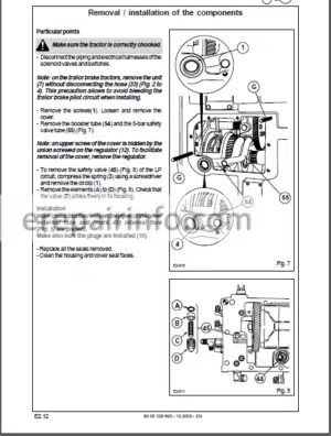
Specific Points Relating To Removaurefitting
–AUXILIARY SPOOL VALVE
Fitting Spool Valves On The Gpa 20 Rear Axle
Hydraulic Diagram Of The Linkage Spool Valve And The Electrohydraulic Spool Valve(’Load Sensing 100 And 110 Umin Circuit)
Hydraulic Diagram Of The Linkage Spool Valve And Mechanical Spool Valve (’Load Sensing 100 And 110 Umin Circuit)
Hydraulic Diagram Of The Linkage Spool Valve And Mechanical Spool Valve (60 Umin Circuit)
4 Position Spool Valve Option ko Zf And Flow Regulator
3 Position Spool Valve Option Zf And Flow Regulator
Electrohydraulically Controlled Spool Valve
Closing Plate With Safety Solenoid Valve
Spool Valve Control Settings
–LINKAGE
Exploded View Of Linkage Spool Valve
Linkage Rams
–BRAKING VALVE
Sectional View Of The Brake Valve (Snr)
Exploded View Of The Brake Valve (Snr)
Removing/Refitting The Brake Valve Snr
Removing/Refitting The Brake Valve Cuna
-0PEN CENTER 60 UMIN
–DESCRIPTION
Characteristics
Operation
High-Pressure Circuit
Low Pressure Steering And Services System
Lubrication System
–COMPONENT LAYOUT
Hydraulic Diagram
Circuit Layout On Beam
Covers
Rh Cover
Lh Cover
–RH COVER
Removal Of Right Cover
Removal/Refitting The Main Pump
Refitting
–LH COVER
Removal
Removal/Refitting The Steering Pump
Refitting
–HYDRAULIC MEASUREMENT AND CHECKING POINTS
Auxiliary Spool Valve Supply Pressure Check
–MEASUREMENT AND CHECKING POINTS
Auxiliary Spool Valve Pressure And Flow Check
–“HYDRAULIC INSPECTION RESULTS” SHEET
Lift Pressure And Brake Valve Check
Auxiliary Spool Valve Pressure And Flow Check
–HYDRAULIC MEASUREMENT AND CHECKING POINTS
Steering Pump Check
Maximum Steering Cylinder Pressure Check
Shockproof Valve Opening Pressure Check
–“HYDRAULIC INSPECTION RESULTS” SHEET
Steering Pump Pressure And Flow Check
Maximum Steering Cylinder Pressure Check
Shockproof Valve Opening Pressure Check
-“LOAD SENSING” 100 UMIN
–DESCRIPTION
Characteristics
Operation
–COMPONENT LAYOUT
Hydraulic Diagram
Circuit Layout On Beam
Covers
Rh Cover
Lh Cover
–RH COVER
External View
Geographical Location Of The Hydraulic Components On The Priority Unit
Pressure Limiter “Dbvl* (210 Bar)
Pressure Limiter “Dbv2″ (175 Bar)
Non-Return Valve ‘rv2‘
Removal
Removal/Refitting The Main Pump
Replacing The Rh Cover
–LH COVER
Removal
Removal/Refitting The Steering Pump
Refitting
–CIRCUIT SELECTOR
Description (‘Load Sensing” Signal)
–HYDRAULIC MEASUREMENT AND CHECKING POINTS
Pressure Check For A Flow Rate Of Less Than 40-Umin And A Flow Rate Of 60 Umin
Standby Pressure Check
Test At 20 Umin
Test At 60 Umin
Minimumimaximum Flow Rate Check On The Auxiliary Spool Valves
Brake Valve Check
–“HYDRAULIC INSPECTION RESULTS” SHEET
Checking The Standby Pressure Of The 14 Cm’ Pump
Check The Pressure For A Required Flow Less Than 40 Umin And A Flow Of 60 Umin
Minimum/Maximum Flow Rate Check On The Auxiliary Spool Valves
–HYDRAULIC MEASUREMENT AND CHECKING POINTS
Maximum Steering Cylinder Pressure Check
Shockproof Valve Opening Pressure Check
–“HYDRAULIC INSPECTION RESULTS” SHEET
Steering Pump Check
Maximum Steering Cylinder Pressure Check
Shockproof Valve Opening Pressure Check
-“LOAD SENSING” 110 UMIN
–DESCRIPTION
Characteristics
General Principle
Main Pump
Pump Regulator
Circuit Selector
–OPERATION
Pressure/Flow Regulation
–COMPONENT LAYOUT
Hydraulic Diagram
Circuit Layout On Beam
Covers
Rh Cover
–PRIORITY UNIT
With Trailer Brake
Without Trailer Brake
–RH COVER
Identification Of Ports And Lines
Exploded View
Removal
Refitting
Adjusting The Speed Sensor
Variable Displacement Pump
–LH COVER
Exploded View
Sectional View
Internal View
Removal
Refitting
–BOOSTER PUMP
Removal
Refitting
Replacement Of Pump Seals
–HYDRAULIC MEASUREMENT AND CHECKING POINTS
Variable Displacement Pump Boost Pressure Check
Standby Pressure And Xls Pressure Check
Maximum Pressure And Flow Rate Check On The Auxiliary Spool Valves
Flow Regulator Check On The Auxiliary Spool Valves
Trigger Pressure Check On The (Ko) Spool Valve
Maximum Rear Lift Pressure Check
Brake Valve Check
–“HYDRAULIC INSPECTION RESULTS” SHEET
Variable Displacement Pump Boost Pressure Check
Standby Pressure And Xls Pressure Check
Maximum Pressure And Flow Rate Check On The Auxilary Spool Valves
Flow Regulator Check On The Auxilary Spool Valves
Trigger Pressure Check On (Ko) Spool Valves
Maximum Rear Lift Pressure Check
–HYDRAULIC MEASUREMENT AND CHECKING POINTS
Steering Pressure Check
Maximum Steering Cylinder Pressure Check
Shockproof Valve Opening Pressure Check
–“HYDRAULIC INSPECTION RESULTS” SHEET
Steering Pressure Check
Maximum Steering Cylinder Pressure Check
Shockproof Valve Opening Pressure Check
-ELECTRICAL SERVICES
–GENERAL CONTENTS
—ITEM LIST – WIRING AND GENERAL LISTS
Item List
Wiring And General Lists
—SCHEMATIC DIAGRAMS ACCORDING TO FUNCTIONS
Schematic Diagrams According To Functions
Fuse And Гe!Зу Box
Earthing Locations
Principle Diagrams
—HARNESS AND CONNECTOR PATHS
Contents
List Of Connectors
Hamess And Connector Paths
Shirt Base
-INSTRUMENT PANEL
–DESCRIPTION
Description Of Panel
–CHARACTERISTICS
Indicator Operation
Engine Temperature Display And Diesel Gauge
Warning Lights
Input/Output By Function
Inputs/Outputs Relating To Indicator Lights
Connection And Functions Of The Wires Of Connectors “Jx1” And ’Jx2′
Instrument Panel Inputs/Outputs
Transmission Oil Pressure Sensor
Blockage Indicator
Engine Oil Pressure Sensor
Transmission Oil Temperature Sensor
Speed Sensors
–REMOVAL/REFITTING
Connectors ’Jx1* And ‘Jx2*
–ADJUSTMENTS
Calibration Over 100 Metres (Refer To Chapter “B* Of The Tractor User’S Manual)
Other Parameter Setting, Error Log Operations, Etc (Refer To Chapter G6”)
-TCE 15 T ELECTRONIC LIFT
–DESCRIPTION
Tce15T
Lift Operating Conditions
Electrical Architecture
Functional Logic
Ecu Inputs And Outputs
Diagnostic And Error Codes
–CHECKS AND ADJUSTMENTS
Connections To Tce 15 T Units
Position Sensor On Gpa 20 Axle
Force Sensor On Gpa 20 Axle
Theoretical Forward Speed Sensor On Gpa 20 Axle
Lift Spool Valve Solenoid Valves
-TCE 15/25 ELECTRONIC LIFT
–DESCRIPTION
TCE15ЯCE25
Access To The Installed Software Version (Tce 15, Tce 25)
Lift Operating Conditions
Error Codes
Electrical Architecture
Ecu Inputs And Outputs
–CHECKS AND ADJUSTMENTS
Connections To Tce 15/Tce 25 Units
Position Sensor
Load Sensor
Theoretical Forward Speed Sensor
Tce 25 Radar
Lift Spool Valve Solenoid Valves
-INFOTRAC AND ISO SOCKET
–PRESENTATION OF THE “INFOTRAC”
Functions
General Description
Operation
Operating Sequence
Schematic Diagram
Functions Of Connector Wires
Outside Air Temperature Sensor
–PRESENTATION OF THE ISO SOCKET
Iso Socket
Iso Unit
Schematic Diagram
Iso Unit Electrical Connections
Functions Of Connector Wires
–REMOVAL/REFITTING AND ELECTRICAL CHECKS
Removing The “Infrtrac” Unit And Changing The Bulbs
Iso Unit And Temperature Sensor
Electrical Check On The Iso Socket
–ADJUSTMENTS
Forward Speed Calibration
Setting ’Infotrac” Parameters
-ELECTROPILOT
–DESCRIPTION
Controls
Electrohydraulic Spool Valve (“Deh”)
Electrical Architecture
Input/Output Settings Console
–SPOOL VALVES
Stack Composition
Hydraulic Diagram
Blanking Plate
–ELECTROHYDRAULIC SPOOL VALVE (“DEH’’)
Description
Operation
–ADDITIONAL TECHNICAL DETAILS
Joystick
Spool Valve Electronics
–REMOVAL/REFITTING
Electrohydraulic Spool Valve (“Deh”)
Control Handle
–CHECK
Error Codes
Joystick Connections
Dc Power Switch Connections
Connections On Module
–MEASUREMENT AND CHECKING POINTS
Checking The Safety Solenoid Valve
Checking The Control Pressures
–“INSPECTION RESULTS” SHEET
Checking The Safety Solenoid Valve
Checking The Control Pressure
-CAB LIFTING AND GLASS BONDING
–DESCRIPTION
Identification
Safety Instructions
Location Of Operations
Summary Of Operations
–REMOVING THE CAB
Preliminary Operations
Removal Operations
Installing The Lifting Bar
Partial Cab Removal Procedure
–REFITTING THE CAB
Special Points
Tightening Torques
Adjustments
–REMOVAL/REFITTING OF GLAZING
Warning!
List Of Equipment To Use – Special Instructions
Removal
Preparing The Windscreen Before Applying Primer
Applying Primer
Preparing The Two-Pack Sealant
Replacing The Ploughing Window
-MANUAL HEATING/AIR CONDITIONING
–CHARACTERISTICS
Cooling Circuit
–GENERAL DESCRIPTION
Diagram Of Operating Principle
–POSITIONING OF COMPONENTS
Positioning Of Components
–DESCRIPTION AND OPERATION
Control Panel
Compressor
Condenser
Drier
Pressure Switch
Expansion Valve
Evaporator
Mechanical Thermostat
Electrical Schematic
–SAFETY INSTRUCTIONS
Safety Instructions
–GAS CHARGING AND DISCHARGING
Tapping Points
–REMOVAL/REFITTING
Removing The Ca8 Front Heating’ajr Conditioning Unit
Removing The Evaporator And Radiator
Removing The Fan
Removing The Expansion Valve
Removing The Drier And Condenser
Refitting
Quantity Of Oil To Be Added When Replacing Components
–DIAGNOSTICS
Test Condition
Minimum Values At An Ambient Temperature Of 20 ‘C
Minimum Values At An Ambient Temperature Of 35 ‘C
Table Of Symptoms
-REGULATED HEATING AND A/C
–CLIMATE CONTROL
Description
Schematic Diagram
Positioning Of Components
Error Codes
Tests
Validation Module Test
Removal/Refitting
-FRONT LIFT LINKAGE AND ATTACHMENT POINTS
–CHARACTERISTICS
Exploded View
–TIGHTENING TORQUES
Tightening Torques
–REMOVAL/REFITTING
Removing The Front Lift Assembly
Removing Side Rails (1) And (2)
Removing The Thust Bar (11)
Removing The Transmission Stiffener (12)
Refitting The Front Lift Assembly
–MEASUREMENT AND CHECKING POINTS
Checking The Cylinder Pressure
–“INSPECTION RESULTS” SHEET
Checking The Cylinder Pressure
–ATTACHMENT POINTS
Attachment Points
-FRONT POWER TAKE-OFF
–CHARACTERISTICS
Characteristics
-FRONT POWER TAKE-OFF UNIT
3 Pinion Assembly Anti-Clockwise (Sitting At The Steering Wgheel)
2 Pinion Assembly Clockwise (Sitting At The Steering Wgheel)
Tightening Torques
Safety Measure
Preliminary Operations
Removing The Housing
Refitting The Housing
–MEASUREMENT AND CHECKING POINTS
Checking The Clutch Feed Pressure
Checking The Solenoid Valve Supply Voltage And Resistance
–“INSPECTION RESULTS” SHEET
Checking The Clutch Feed Pressure
Checking The Solenoid Valve Supply Voltage And Resistance
-PNEUMATIC BRAKE
–GENERAL DESCRIPTION
Benefits
–PRESENTATION OF THE DIFFERENT SYSTEMS
Single Pipe System
2 Pipe System
–TECHNOLOGICAL CONCEPTS
Coding Of Ports
Symbolic Representation
Schematic Diagram
Compressor
Pressure Regulator
Tank
Solenoid Valve
Principal Control Valve
Trailer Control Valve
–DESCRIPTION
Black Hand
Red And Yellow Hands
What you get
You will receive PDF file with high-quality manual on your email immediately after the payment.


Anonymous (verified owner) –
Great service fast and informative just as described