


Factory Service Repair Manual For Claas Renault Ares 816 Tractor. Tons of illustrations, instructions, diagrams for step by step remove and install, assembly and disassembly, service, inspection, repair, troubleshooting, tune-ups.
Format: PDF
Language: English
Pages: 1271
Bookmarks: Yes
Searchable: Yes
Wiring Diagrams: Yes
Hydraulic Diagrams: Yes
Model
Claas Renault Ares 816
Contents
- -INJECTION SHEET CHECKING PROCEDURE
–CHECKING PROCEDURE
Checking Procedure
–MEASUREMENT SHEET
Measurement Sheet
–PRESSURE CONNECTION (APPENDIX)
100 B’minls Circuit
110 L’min Ls Circuit - -INJECTION FEED
–IDENTIFICATION
Injection Pumps Identification
–TIGHTENING TORQUES
Tightening Torques
–OPERATING PRINCIPLES
Pre-Filter
Fuel Filter
Injection Pump
Injectors
Situation Of The Different Sensors
–CHECKS/ADJUSTMENTS
Accelerator Control Adjustment
Adjusting The Engine Injector
Supply Pressure Check
–REMOVAL/REFITTING
Fuel Filter Replacement
Injection System Bleeding
Injection Pump Removal
–DIAGNOSTICS
Sheet Ne 1 “Engine Start-Up Defect”
Sheet Ne 2 “Irregular Engine Operation”
Sheet Ne 3 “Grey Or Black Smoke Emission”
Sheet Ne 4 “White Smoke Emission”
Sheet Ne 5 “Check The Fuel Feed Circuit” - -ENGINE TIER II
–GENERAL SPECIFICATIONS
Identification Of The Engines
Engines 6 Cylinders
–DIMENSIONAL SPECIFICATIONS
Cylinder Head And Valves
Cylinder Block
Liners And Pistons
Connecting Rods
Crankshaft Bearingsand Flywheel
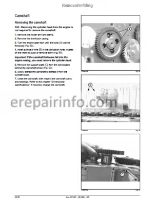
Camshaft
Distribution
Lubrication
Cooling
Turbocharger
–TIGHTENING TORQUES
Front Chassis/ Engine Link
Enginbtransmission Link
Crankshaft With Straight Front End
Crankshaft With Tapering Front End
–CHECKS/ADJUSTMENTS
Checking Compression
Check Of Engine Oil Pressure
Check Of Valve Lift (Engine Cold)
Valve Clearance (Engine Cold)
Valve Adjustment Sequence
Checking The Turbocharger Pressure
Check Of The Belt And The Tensioner Spring
Procedure For Checking The Viscous Fan Coupling
–REMOVAL/REFITTING
Preliminary Operations
Separate Enginefront Axle
Separate Enginbgearbox
Engine Installation Specifications
Cylinder Head
Camshaft
Cylinder Block
Liners
Pistons And Connecting Rods
Crankshaft Bearings And Flywheel
Changing The Front Bearing Seal
Camshaft Balancer Shafts And Distributor
Lubrication
Cooling
Turbocharger
–DIAGNOSTIC SHEETS
“Excessive Oil Consumption’ Sheet
Inspection Procedure Of The Cylinder Head Gasket
“Engine Oil Pressure Too High’ Sheet
Checking Procedure Of The High Oil Pressure In The Crankcase
“Engine Oil Pressure Too Low Sheet
“Coolant Temperature Too High” Sheet
“Coolant Temperature Too Low” Sheet
Failure Searching Procedure Of Cylinder Head Seal
–TOOLS
Engine Tools - -GBA 10 GEARBOX
–GENERAL SPECIFICATIONS
Meaning Of Transmission System Designations
Introduction To The Gba 10
Transmission Kinematics
Gta 1041 Overdrive
Gta 1042 And 42+ Overdrive
Gta 1044 Overdrive
Gta 1044 Non-Overdrive
Gba 10 Removalrefitting Procedure
–TIGHTENING TORQUE
Enginb’gearbox Coupling
Gearboxrear Axle Coupling
–MAIN ADJUSTMENTS
Main Adjustments
–REVERSHIFT
Clutch Function
Shuttle Reverser Operaton
–FRONT CLUTCH
Exploded View
Removal/Refitting (Stage 1 Page B19)
Removal
Refitting
Adjustment
Preparing For Adjustment
–REAR CLUTCH
Exploded View
Removal/Refitting (Stage 2 Page B19)
Removal
Refitting The Epicyclic Gear Set
Refitting The Assembly
–QUADRISHIFT UNIT
Operating Diagram
Exploded View
Removal/Refitting (Stage 3 Page Bl 9)
Removing The Front Brake And Clutch
Removing The Planet Carrier Assembly
Assembling The Planet Carriers
Removing The Rear Brake And Clutch
Removing The Secondary Shaft
Refitting And Adjusting The Secondary Shaft
Refitting The Rear Brake And Clutch
Refitting The Front 8Rake And Clutch
Adjusting The Planet Carrier
Refitting The Quadrishift Unit
–GEARSHIFT COVER
General
Removing/Refitting The Cover
Replacing The Range Piston Seals
Removing And Refitting The Gear Selector
Adjusting The Field’road Range
–GUIDE RODS
General
Exploded View
Removing The Guide Rods
Refitting The Guide Rods
Adjusting The Forks
–OUTPUT SHAFT
General
Exploded View
Removing The Shaft
Refitting The Shaft
Adjusting The Shaft
–INPUT SHAFT
General
Exploded View
Removing The Shaft
Removing The Shaft
Refitting The Shaft
Adjusting The Shaft
–COUNTERSHAFT
General
Exploded View
Removing The Shaft
Adjusting The Shaft
Refitting The Shaft
Adjusting The Bearings
–CRAWLER SPEEDS
General
Exploded View
Removing/Refitting The Housing
Removing Adjusting And Refitting The Control System
Setting The Controls - -GTA 1040 AND GPA 30 LOW-PRESSURE HYDRAULIC CIRCUIT
–LS 100 UMIN LOW-PRESSURE CIRCUIT ON GTA 1040
Circuit Layout On Beam
Hydraulic System
Gearbox And Rear Axle Lubrication
Axle Tube Lubrication
–LS 110 UMIN LOW-PRESSURE CIRCUIT ON GTA 1040
Circuit Layout On Beam
Hydraulic System
Gearbox And Rear Axle Lubrication
Axle Tube Lubrication
–LS 110 UMIN LOW-PRESSURE CIRCUIT ON GPA 30
Circuit Layout On Beam
Hydraulic System
Rear Axle Lubrication
Axle Tube Lubrication
–LOW-PRESSURE HYDRAULIC COMPONENTS
Ls 100 Umin Distribution Valve
Ls 110 Umin Distribution Valve
Revershift And Quadrishift Control
Independent Lubrication On Gba 10
–SOLENOID VALVE MEASUREMENT AND CHECKING POINTS
Electrical Tests On The Solenoids
–GBA 10 DISTRIBUTION UNIT MEASUREMENT AND CHECKING POINTS
Distribution Unit Supply Pressure Check
Revershift Supply Pressure Check
Quadrishift Supply Pressure Check
–“HYDRAULIC INSPECTION RESULTS” SHEET
Hydraulic Inspection Results Sheet
–GBA 10 LUBRICATION MEASUREMENT AND CHECKING POINTS
Independent Lubrication Check
–“HYDRAULIC INSPECTION RESULTS” SHEET
Hydraulic Inspection Results Sheet
–LS 110 L/MIN MEASUREMENT AND CHECKING POINTS
Lubrication Pressure Check
Gba 10 Lubrication Pressure Check
Checking The Control Pressure
Lubricating Oil Flow Rate Through The Cooler At 60‘C
–“HYDRAULIC INSPECTION RESULTS” SHEET
Hydraulic Inspection Results’ Sheet
–LS 100 L/MIN MEASUREMENT AND CHECKING POINTS
Checking The Flow Coming From The Steering Box
Checking The Control Pressure
Cooler Inlet Pressure Check
Lubrication Pressure Check
–“HYDRAULIC INSPECTION RESULTS” SHEET
Hydraulic Inspection Results Sheet
-GBA 31 FULL POWERSHIFT GEARBOX
–GENERAL
Characteristics
Description Of The Transmission System
Gearbox Arrangement Diagram
Operation And Power Transmission
–REPAIR
Replacing The Input Shaft Seal
Removing The Gearbox Completely
Tightening Torques - -FULL POWERSHIFT LOW PRESSURE HYDRAULIC CIRCUIT
–GENERAL
Operation
Characteristics
–DESCRIPTION
Transmission Hydraulic Circuit
Transmission Circuit Layout
Oil Filter
Thermostatic Valve
–REPAIR
Pump Gerotor Type
Pressure Control Valve
Proportional Solenoid Valve
Discharge Valve
–MEASUREMENT AND CHECKING POINTS
Checking The Control Pressure
Lubrication Pressure Check
Checking The Clutch Feed Pressures
Electrical Check On The Solenoids
–“INSPECTION RESULTS” SHEET
“Inspection Results” Sheet
–TOOLS
Low-Pressure Hydraulics And Gearbox Tools - -GPA 40 REAR AXLE
–TIGHTENING TORQUES AND MAIN ADJUSTMENTS
Gearbox’rear Axle Coupling
Rear Axle’pto Housing Coupling
General Cross-Section
5′ Differential
Nd Axle Tubes
Hd And Hd+Axle Tubes
Hde Axle Tubes
–GPA 40 DRIVE PINION
General
Removal/Refitting
Setting And Adjusting The Protrusion Distance Of The Drive Pinion
–5″ DIFFERENTIAL
General
Removing/Refitting The Bearings
Removing/Refitting The Differential Case
Removing/Refitting The Differential Lock
Removing/Refitting The Planet Gears Sun Gears And Ring Gear
Adjusting The Backlash
Shimming The Differential Case Roller Bearings
–ND AXLE TUBES
General
Removal
Refitting
Removing The Planet Carrier
Refitting The Planet Carrier
Removing The Roller Bearings And Seals
Refitting The Roller Bearings And Seals
Shimming The Wheel Shaft Bearings
Replacing The Wheel Stud
–HD AND HD+ AXLE TUBES
General
Removal
Refitting
Removing The Planet Carrier
Refitting The Planet Carrier
Removing The Roller Bearings And Seals
Refitting The Roller Bearings And Seals
Shimming The Wheel Shaft Bearings
Replacing The Wheel Stud
–HDE AXLE TUBES
General
Removal
Refitting
Removing The Planet Carrier
Refitting The Planet Carrier
Removing The Roller Bearings And Seals
Refitting The Roller Bearings And Seals
Shimming The Wheel Shaft Bearings
Replacing The Wheel Stud
–GPA 40 POWER TAKE-OFF CLUTCH
General
Removal/Refitting
Removing The Clutch
Refitting The Clutch
–GPA 40 POWER TAKE-OFF UPPER SHAFT
General
Prevention System
Removal/Refitting
Removal/Refitting
Adjustment
Adjusting The Controls
–GPA 40 POWER TAKE-OFF LOWER SHAFT
General
Power Take-Off Brake
Removing/Refitting The Lower Shaft
Adjustment
–PROPORTIONAL POWER TAKE-OFF
General
Removing/Refitting The Selection System
Removing/Refitting The Gears
Adjusting The Bearings - -GPA 30 REAR AXLE
–TIGHTENING TORQUES AND MAIN ADJUSTMENTS
Gearbox Intermediate Housing Coupling
Intermediate Housing’rear Axle Coupling
Rear Axle’pto Housing Coupling
General Cross-Section
5′ Differential
Hd+Axle Tubes
Hde Axle Tubes
–GPA 30 DRIVE PINION
General
Removal/Refitting
Drive Pinion Protrusion Distance And Shimming
–5″ DIFFERENTIAL
General
Removing/Refitting The Bearings
Removing/Refitting The Differential Case
Removing/Refitting The Differential Lock
Removing/Refitting The Planet Gears Sun Gears And Ring Gear
Adjusting The Backlash
Shimming The Differential Case Roller Bearings
–GPA 30 POWER TAKE-OFF CLUTCH
General
Removal/Refitting
Removing The Clutch
Refitting The Clutch
–GPA 30 POWER TAKE-OFF UPPER SHAFT
Removal/Refitting
Adjustment
Gpa 30 Power Take-Off Lower Shaft
General
Removal
Refitting
Adjusting The Bearings
–GPA 30 CRAWLER GEARS
General
Removing/Refitting The Housing
Removing Adjusting And Refitting The Control System
Setting The Controls - -SERVICE BRAKES
–TECHNICAL SPECIFICATIONS
Footbrake
–BRAKE PISTONS AND SEALS
Draining The Service Brake Circuit
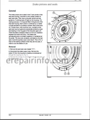
General
Removal
Refitting
Sealing Test
–BOOSTERS AND MASTER CYLINDERS
Description Of The Master Cylinders/Boosters
–REPLACING THE MASTER CYLINDERS
Adjusting The Brake Pedals
–BLEEDING THE BRAKE CIRCUIT
Bleeding The Circuit Manually
Closed-Centre Hydraulic Circuit On Gta 3130 (Ls 110 L/Min)
Closed-Centre Hydraulic Circuit On Gta 1040 (Ls 110 L/Min)
Closed-Centre Hydraulic Circuit On Gta 1040 (Ls 100 L/Min)
Bleeding The Brake Circuit With A Pressurising Device
Checking The Effectiveness Of The 110 L’min And 103 L/Min Circuit Air Bleed (Bosch Valve)
Checking The Snr Valve (100 Umin Circuit) - -AUTOMATIC BRAKE PARK LOCK AND HANDBRAKE
–AUTOMATIC BRAKE
Operating Principles
Exploded View Of Control Unit
Exploded View Of Brake Mechanism
Removing/Refitting The Automatic Brake Assembly
Removing/Refitting The Unit
Removing/Refitting The Parking Brake
Basic Parking Brake Adjustment
Adjusting The Parking Brake Control
–PARK LOCK
General
Remark
Overall View
Schematic Diagram
Operation
Removing/Refitting The Safety Switch
Safety Switch Adjustment
“Inspection Results” Sheet
–HANDBRAKE
General
Operation
Exploded View
Removing And Refitting The Handbrake Casing
Adjusting The Handbrake Control
Diagnosing Brake Disc Wear
Remark
–TOOLS
Gpa 40 Rear Axle – Gpa 30 Rear Axle – Service Brakes – Automatic Brake – Park Lock -Handbrake - -FRONT AXLE
–DESCRIPTION
General Characteristics – Rigid Axle
Drive Chain
–REMOVAL/REFITTING
Tightening Torques And Sealants
Adjusting The Wheel Alignment
–DISASSEMBLY PRIOR TO FRONT AXLE OPERATIONS
Preliminary Operations
–REMOVAL/REFITTING
Steering Cylinder
Removing The Reduction Gear And Wheel Hub
Refitting The Reduction Gear And Wheel Hub
Removing The Wheel Pivot
Refitting The Wheel Pivot
Refitting The Angle Sensor
Removing The Bevel Gear And Differential
Disassembling The Differential
Adjusting The Pinion Protrusion Distance
Setting The Bevel Pinion Preload
Adjusting The Meshing Backlash
Preloading The Differential Bearing Blocks
Checking The Settings
Final Reassembly
–HYDRAULIC MEASUREMENT AND CHECKING POINTS
Checking The Differential Lock Circuit Pressure
–“HYDRAULIC INSPECTION RESULTS” SHEET
Checking The Differential Lock Circuit Pressure - -PROACTIV FRONT AXLE
–DESCRIPTION
General Characteristics – Rigid Axle
Characteristics
–REMOVAL/REFITTING
Tightening Torques And Sealants
Adjusting The Wheel Alignment
–DISASSEMBLY PRIOR TO FRONT AXLE OPERATIONS
Preliminary Operations
–REMOVAL/REFITTING
Steering Cylinder
Epicyclic Reduction Gear And Wheel Hub
Removing The Epicyclic Reduction Gear
Removing The Wheel Hub
Wheel Pivot And Upper Arm
Removing The Angle Sensor
Removing The Wheel Pivots
Removing The Upper Arm
Suspension Cylinder And Lower Arm
Removing The Torsion Bar
Removing The Lower Arm
Refitting The Lower Arm
Refitting The Torsion Bar
Refitting The Upper Arm
Universal Shafts
Refitting The Wheel Pivots
Refitting The Wheel Hub
Refitting The Epicyclic Reduction Gear
Refitting The Suspension Position Sensor
Setting The Suspension Sensors
Locally Made Test Harness
Calibrating The Suspension
Refitting The Angle Sensor
Final Steps
Bevel Gear And Differential
Sectional View
Exploded View
Disassembling The Differential
Adjusting The Pinion Protrusion Distance
Setting The Bevel Pinion Preload
Adjusting The Meshing Backlash
Checking The Settings
Final Reassembly
Suspension Control Unit
–HYDRAULIC MEASUREMENT AND CHECKING POINTS
Suspension Cylinder Pressure Check
Checking The Differential Lock Circuit Pressure
–HYDRAULIC MEASUREMENT AND CHECKING POINTS
Suspension Cylinder Pressure Check
Differential Locking Circuit Pressure Check
–ELECTRIC CHECKS
Control Switches
Suspension Control Solenoids
–BREAKDOWN DIAGNOSIS
Values To Be Checked
Interpreting Error Codes - -GPA 30 AND GPA 40 4-WHEEL DRIVE POWER TAKE-OFF HOUSING
–DESCRIPTION
General
Cross-Sectional View Of The 4-Wheel Drive Housing (Gpa 30 Axle)
Cross-Sectional View Of The 4-Wheel Drive Housing (Gpa 30 Axle)
Exploded View Of The 4-Wheel Drive Housing (Gpa 30 Axle)
Cross-Sectional View Of The 4-Wheel Drive Housing (Gpa 40 Axle)
Cross-Sectional View Of The 4-Wheel Drive Housing (Gpa 40 Axle)
Exploded View Of The 4-Wheel Drive Housing (Gpa 40 Axle)
–REMOVING/REFITTING THE HOUSING
Removal Of Clutch
Removing The Clutch
Refitting The ClutchI
Fitting Shims To The Clutch “Ji”I
Fitting Shims To The Shaft ’J2″I
Refitting The ShaftI
–SOLENOID VALVE MEASUREMENT AND CHECKING POINTS
Owoff Solenoid ValveI
–HYDRAULIC MEASUREMENT AND CHECKING POINT
Checking The Front Axle Engagement PressureI
–“HYDRAULIC INSPECTION RESULTS” SHEET
Checking The Front Axle Engagement PressureI
–TOOLS
Front Axle – 4 Wd Power Take-Off Housing - -CLOSED CENTRE HYDRAULICS (110 L/MIN)
–DESCRIPTION
Characteristics
Hydraulic Circuit Diagram – Quadrishift Transmission
Component Layout – Quadrishift Transmission
Hydraulic Circuit Diagram – Full Powershift Transmission
Component Layout – Full Powershifttransmission
Sectional View Of Gpa 40 Rear Axle
Sectional View Of Gpa 30 Rear Axle
–REMOVING/REFITTING THE COMPONENTS
External View Of Right-Hand Cover Without Brake Valve
External View Of Right-Hand Cover With Brake Valve
Internal View Of Right-Hand Cover
Exploded View Of Right-Hand Cover
Identification Of Ports And Lines
Schematic Diagram Of The Variable Displacement Pump Regulator
Priority Unit (No Trailer Brake)
Priority Units (With Trailer Brake)
Schematic Diagram Of Priority Units
Removal Of Right Cover
Replacing The Rh Cover
Adjusting The Speed Sensor
Variable Displacement Pump
Exploded View Of The Left-Hand Cover
Sectional View Of The Left-Hand Cover
Sectional View Of The Gpa 30 Left-Hand Cover
Sectional View Of The Gpa 40 Left-Hand Cover
Removal Specifications
Refitting Specifications
Booster Pump
Replacement Of Pump Seals
Fitting Spool Valves On The Gpa 40 Rear Axle
Fitting Spool Valves On The Gpa 30 Rear Axle
Hydraulic Diagram Of The Lift Spool Valve And The Electrohydraulic Spool Valve
Hydraulic Diagram Of The Lift Spool Valve And Mechanical Spool Valve
Removing The Spool Valve Block
Refitting The Spool Valve Unit
Linkage Spool Valve
Linkage Spool Valve (Neutral Position)
Linkage Spool Valve (Down Position)
Linkage Spool Valve (Up Position)
3-Position “Zp Auxiliary Spool Valve With Optional ‘ko*
Four-Position “Zp Auxiliary Spool Valve
4-Position ’Zp Auxiliary Spool Valve With Optional T<0*
Auxiliary Spool Valve With Electrohydraulic Controls
Closing Plate With Safety Solenoid Valve
Auxiliary Spool Valve Control Adjustments
Linkage Rams
Steering Unit Ospq 100/160 Ls (110 Bmin Circuit)
Exploded View Of Steering Unit Ospq 100’160 Ls (110 L/Min Circuit)
Hydraulic Diagram Of Steering Unit Ospq 100/160 Ls (110 L’min Circuit)
Steering Unit Ospc 135 On (100 Bmin Circuit)
Exploded View Of Steering Unit Ospc 135 On (100 L’min Circuit)
Hydraulic Diagram Of Steering Unit Ospc 135 On (100 Bmin Circuit)
Access To Steering Unit
Specific Points Relating To Removabrefitting
–HYDRAULIC MEASUREMENT AND CHECKING POINTS
Variable Displacement Pump Boost Pressure Check
Standby Pressure And ’Xls* Pressure Check
Maximum Pressure And Flow Rate Check On The Auxiliary Spool Valves
Flow Regulator Check On The Auxiliary Spool Valves
Trigger Pressure Check On The (Ko) Spool Valve
Maximum Rear Lift Pressure Check
Braking Valve Check
–“HYDRAULIC INSPECTION RESULTS” SHEET
Variable Displacement Pump Boost Pressure Check
Standby Pressure And ’Xls* Pressure Check
Maximum Pressure And Flow Rate Check On The Auxiliary Spool Valves
Flow Regulator Check On The Auxiliary Spool Valves
Trigger Pressure Check On (Ko) Spool Valves
Maximum Rear Lift Pressure Check
–HYDRAULIC MEASUREMENT AND CHECKING POINTS
Steering Pressure Check
Maximum Steering Cylinder Pressure Check
Shockproof Valve Opening Pressure Check
–“HYDRAULIC INSPECTION RESULTS” SHEET
Steering Pressure Check
Maximum Steering Cylinder Pressure Check
Shockproof Valve Opening Pressure Check - -CLOSED CENTRE HYDRAULICS (100 L/MIN)
–DESCRIPTION
Characteristics
General Hydraulic Circuit Diagram Of 100 L “Load Sensing” Closed-Centre Circuit
Hydraulic Circuit Diagram – Quadrishift Transmission
Exterior View Of The Right-Hand Cover
Interior And Exterior View Of The Right-Hand Cover
Description Of The Circuit Selector (Load Sensing Signal)
–REMOVING/REFITTING THE COMPONENTS
Brake Valve
Sectional View Of The Braking Valve (Bosch)
Exploded View Of Braking Valve (Bosch)
Sectional View Of The Braking Valve (Snr)
Exploded View Of Braking Valve (Snr)
Geographical Location Of The Hydraulic Components On The Priority Unit
Pressure Limiter Dsvl (210 Bar)
Removal Of Right Cover
Removal/Refitting The Main Pump
Replacing The Rh Cover
Overall View Of The Left-Hand Cover
Removing The Left-Hand Cover
Refitting The Left-Hand Cover
Removal/Refitting The Steering Pump
–HYDRAULIC MEASUREMENT AND CHECKING POINTS
Checking The Standby Pressure Of The 14 Cm’ Pump
Pressure Check For A Flow Rate Of Less Than 40-Umin And A Flow Rate Of 60 L’min
Test At 20 Umin
Test At 20 Umin
Minimum/Maximum Flow Rate Check On The Auxiliary Spool Valves
Braking Valve Check
–“HYDRAULIC INSPECTION RESULTS” SHEET
Minimum/Maximum Flow Rate Check On The Auxiliary Spool Valves
Checking The Standby Pressure Of The 14 Cm’ Pump
Check The Pressure For A Required Flow Less Than 40 Umin And A Flow Of 60 L’min
–HYDRAULIC MEASUREMENT AND CHECKING POINTS
Checking The Steering Pump
Maximum Steering Cylinder Pressure Check
Shockproof Valve Opening Pressure Check
–“HYDRAULIC INSPECTION RESULTS” SHEET
Checking The Steering Pump
Maximum Steering Cylinder Pressure Check
Shockproof Valve Opening Pressure Check
–TOOLS
Hydraulic Circuit Tooling
-ELECTRICITY
–GENERAL CONTENTS
Item List
Wiring And General Lists
Schematic Diagrams According To Functions
Connector And Harness Tracking
–TOOLS
Electricity Tools
-INSTRUMENT PANEL
–OPERATING PRINCIPLES
Description Of Panel
Allocation Of Light Bulbs To Indicator Lights
–CHARACTERISTICS
Indicator Operation
Warning Lights (Red)
Secondary Warning Lights (Orange)
Other Indicator Lights
Input’output By Function (Rev Counter Various Speeds And Hour Counter)
Input’output By Function (Gauge And Temperature)
Input&’outputs Relating To Red Lights
Input&’outputs Relating To Other Lights
Connection And Functions Of The Wires Of The Single Connector ‘jxv
Connection And Functions Of The Wires Of The Double Connector *Jx2*
Transmission Oil Pressure Sensor (17 Bar)
Blockage Indicator
Engine Oil Pressure Sensor
Transmission Oil Temperature Sensor
Speed Sensors
–REMOVAL/REFITTING
Connectors ‘jxl’And ’Jx2’ - -CALIBRATION
Calibration Over 100 Metres
Other Operations
-TCE 15/25 AND TCE 15 T ELECTRONIC LIFT
–DESCRIPTION
Tce 15/Tce25
Access To The Installed Software Version (Tce 15 Or Tce 25)
Lift Operating Conditions
Error Codes
Tce 15T
Lift Operating Conditions
Error Codes
–CHECKS AND ADJUSTMENTS
Connections To Tce 1ЭTCE 25 Units
Connections To Tce 15T Unit
Position Sensor On Gpa 30 Axle
Position Sensor On Gpa 40 Axle
Draft Sensor On Gpa 30 And Gpa 40 Axles
Theoretical Forward Speed Sensor On Gpa 30 And Gpa 40 Axles
Radar (Tce 25 Only)
Lift Spool Valve Solenoid Valves - -TRANSMISSION/AXLE CONTROL
–DRIVETRONIC III
Location Of The Ls 1OЭ L/Min Components And Sensors
Location Of The Ls 110 L/Min Components And Sensors
Toc Boc Switches And Angle Detector
Drivetronic Electronic Unit
Shuttle Reverser Lever Characteristics (Illustrated In Neutral)
Range And Declutching Control
Clutch Pedal Switches
Quadrishift Ii (244) And Quadractiv (245) Control Switches
Solenoid Valve
Control Pressure Switch
Lubricatiomboost Pressure Switch 3 Bar
Blockage Indicator
Speed Sensors
Temperature Sensor
Adjustment Of Toc Boc And Angle Detector Switches
Static Calibration Of Clutches
Adjusting The Calibration Procedures
Inputs/Outputs By Functions And Automatic Systems
Steering Angle Calibration
General Schematic Diagram
–DRIVETRONIC V
Inputs/Outputs And Automatic Systems
Switch And Solenoid Valve Check
Error Codes
–FULL POWERSHIFT
Location Of Components And Sensors
Layout On The Rear Axle
Features/Settings
Clutch Pedal Switches
Schematic Diagram Of Tc/Rcc - -ENGINE MANAGEMENT
–DE 10 PUMP
Location Of Components And Sensors
Characteristics Of The Components
Adjusting The Accelerator Detector
Diagnostic Harness
–VP 44 PUMP
Location Of Components And Sensors
Characteristics Of The Components
Schematic Diagram
Adjusting The Accelerator Detector
Diagnostic Harness - -ENGINE MANAGEMENT
–DE 10 PUMP
Location Cf Components And Sensors
Characteristics Of The Components
Adjusting The Accelerator Detector
Diagnostic Harness
–VP 44 PUMP
Location Of Components And Sensors
Characteristics Of The Components
Schematic Diagram
Adjusting The Accelerator Detector
Diagnostic Harness - -INFOTRAC AND ISO SOCKET
–DESCRIPTION
Functions Of The On-Board Computer
Operating Principles
Use
–REMOVAL/REFITTING AND ELECTRICAL CHECKS
Removing The Unit And Changing The Bulbs
Iso Socket
Iso Unit
External Temperature Probe
Schematic Diagram
Functions Of Connector Wires
Electrical Check On The Iso Socket
Outside Air Temperature Sensor
Forward Speed Calibration
Maintenance Function - -ELECTROPILOT
–DESCRIPTION
Controls
Joystick Connections
Dc Power Switch Connections
Connections On Module
Electrohydraulic Spool Valve (‘deh”)
–REMOVAL/REFITTING
Electrohydraulic Spool Valve (‘deh”)
Control Handle
–MEASUREMENT AND CHECKING POINTS
Checking The Safety Solenoid Valve
Checking The Control Pressures
–“INSPECTION RESULTS” SHEET
Checking The Safety Solenoid Valve
Checking The Control Pressure
–TOOLS
Instrument Panel – Electronic Lift (And Radar) – Transmission’axle Control – Engine Management – Infotrac And Iso Socket – Electropilot - -CAB LIFT
–DESCRIPTION
Identification
Right Side (Location Of Operations)
Left Side (Location Of Operations)
–FULL CAB REMOVAL
Safety Measure
Sling Specifications
–REMOVAL/REFITTING
Operations 1 To 4
Preparing The Lifting Bar
Installing The Lifting Bar
Taking The Weight Of The Cab
Operations 5 To 6
Operations 7 To 9
Operations Wto 12
Operations 13 To 14
Operations 15 To 18
Operation N* 19
Operation № 20
Operation N* 21
–REFITTING THE CAB
Special Points
Tightening Torques
Adjustments
–REMOVING/REFITTING THE ROOF
Full Removal With The Air Conditioning Fans
Refitting - -HEATING/AIR CONDITIONING
–DESCRIPTION
Characteristics
Diagram Of Operating Principle
Control Panel
–REMOVAL/REFITTING
Engine Layout
Cab Layout
Heating Radiator Unit And Fans
Heating Radiator
–TROUBLESHOOTING GUIDE
Diagnostics - -BONDING THE WINDOWS
–REMOVAL/REFITTING
Warning!
List Of Equipment To Use – Special Instructions
Removal
Preparing The Windscreen Before Applying Primer
Applying Primer
Preparing The Two-Pack Sealant
Replacing The Ploughing Window
–TOOLS
Cab Lift – Heating/Air Conditioning – Bonding The Windows - -LIFT AND FRONT POWER TAKE-OFF
–FRONT LIFT
Characteristics
Exploded Views Of 3 500 And 6 600 Dan Front Lifts
Tightening Torques
–MEASUREMENT AND CHECKING POINTS
Checking The Cylinder Pressure
–“INSPECTION RESULTS” SHEET
Checking The Cylinder Pressure
–FRONT POWER TAKE-OFF
Characteristics
Exploded View Of The Front Power Take-Off Assembly
Exploded View Of The Unit
Removing The Pto Housing
Exploded View Of The Clutch
Removing The Clutch
Refitting The Clutch
–MEASUREMENT AND CHECKING POINTS
Checking The Clutch Feed Pressure
–“INSPECTION RESULTS” SHEET
Checking The Clutch Feed Pressure - -PNEUMATIC BRAKING
–HOW IT WORKS
Measurement And Checking Points
With The Engine Running And Trailer Connected No Action Of Brakes
With The Engine Running And Trailer Connected Service Brakes Applied
With The Engine Running And Trailer Connected Hand Brake Applied
–MAIN COMPONENTS
Pneumatic Circuit Layout On Gta 3230
Compressor
Pressure Regulator
Tank
Trailer Control Valve
Solenoid Valve
Principal Control Valve
Bleeding The Hydraulic And Pneumatic Trailer Braking System
–TOOLS
Lift, Front Power Take-Off And Pneumatic Braking Tools
What you get
You will receive PDF file with high-quality manual on your email immediately after the payment.


Reviews
There are no reviews yet.