


Factory Service Repair Manual For Claas Renault Temis 550 610 630 650 Tractors. Tons of illustrations, instructions, diagrams for step by step remove and install, assembly and disassembly, service, inspection, repair, troubleshooting, tune-ups.
Format: PDF
Language: English
Bookmarks: Yes
Searchable: Yes
Wiring Diagrams: Yes
Hydraulic Diagrams: Yes
Model
Claas Renault Temis 550, 610, 630, 650
Contents
-INJECTION SHEET
Temis 550
Temis 610
Temis 630
Temis 650
-INJECTION SUPPLY
–IDENTIFICATION
Stanadyne Injection Pump
–SECTION DRAWINGS
Rotary Inject On Pump
Injectors
–SPECIFICATIONS
General Specificatons
–TIGHTENING TORQUES
Tightening Toroue Values
–OPERATING PRINCIPLES
Supply
Fuelfilter
Injectors
Injection Pump
–Checks – Adjustments
Engine Speed
Static Adjustment Of The Rotary Injection Pump
Dynamicadjustment Of The Rotary Injection Pump
Injectoradjustment
Cracking Pressure Adjustment
Needle Stroke Adjustment
Supply Pressure Check
Shut-Off Solenoid Valvefunctional Check
Cold-Start Accele Raton Device Operating Principle
Cold-Start Switch Functonalcheck
–REMOVAL – INSTALLATION
Fuel Filter Replacement
Injection System Bleeding
Rotary Inject On Pump Removal
Rotary Injection Pump Installation
Injector Removal
Injector Seatingcleaning
Injector Installation
Carrying Overof The Adjustment Mark Ontothefront Plate
Template For Front Plate Marking
Adjustment Of Controls
Acceleratorcontrol
–TOOLS
Tools
Special Tools
-INJECTION SUPPLY
–IDENTIFICATION
Injection Pump Identification
–SECTION DRAWINGS
Injection Pump Longitudinal Section
–SPECIFICATIONS
Main Specifications
–TIGHTENING TORQUES
Tightening Torques
–OPERATING PRINCIPLE
Supply
Fuel Filter
Injection Pump
–CHECKS – ADJUSTMENTS
Engine Speed
Static Adjustment Of The Rotary Injection Pump
Injectoradjustment
Supply Pressurecheck
Shut-Off Solenoid Valve Functional Check
–REMOVAL – INSTALLATION
Fuel Filter Replacement
Supply System Bleeding
Rotary Injection Pump
Injector Seating
–ADJUSTMENT OF CONTROLS
Accelerator Control
–TOOLS
Injector Tools
-D.P.S. ENGINE
–IDENTIFICATION
Engine Identfication
–CROSS SECTIONS
Transverse section
Longitudinal section
–SPECIFICATIONS
General Specifications
Dimensional Specifications
Cylinder Head And Vatves
Cylinder Block, Liners, Pistons And Connecting Rods
Crankshaft, Bearings And Flywheel
Camshaft And Distributor
Lubricaton
Cooling
Turbocharger
–TIGHTENING TORQUES
Cylinder Head And Vatves
Cylinder Block, Linersand Connecting Rods
Crankshaft, Bearings And Flywheel
Camshaft And Distributor
Lubricaton
Cooling
Inlet And Exhaust
Enginearansmission Link
Front Chassis/Engine Link
–OPERATING PRINCIPLE
Distribution
Lubrication
Cooling
–CHECKS – ADJUSTMENTS
Compression Check
Engine Oil Pressure Check
Valve Lift Check (Engine Cold)
Valve Clearance (Engine Cold)
Valve Adjustment Sequence
Tu Rboch Arger Pr Essu Re Ch Eck
Belt Tensioner Spring Tension And Belt Wear Checks
–DISASSEMBLY – ASSEMBLY
CYLINDER HEAD
Cylinder Head Removal
Injector Seating Cleaning
Remwalofvalves And Valve Springs
Inspection Of The Cy Tender Head Seal Surface
Cylinder Head Reinstallation
Tigtile Ring Procedure
Angular Teetering Procedure
Reinstallation Al Therocker Arm Assembly (Only After Reinstalling The Cylinderhead)
–CAMSHAFT
Camshaft Removal
–CYLINDER BLOCK
Replacementof Tie Camshaft Bush
–LINERS
Liner Remwal
Ovality And Taper Check On Liners
Measurement Ofliner Protrnsion
Installation Of Square-Section Seal
Installation Of Liner O-Rings
Liner Reinstallation
–PISTONS AND CONNECTING RODS
Connecting Rods-General
Replacement Of Small End Bushes
Inspection Of Piston Heads And Skirts
Top Compression Ring Groove
Pistons And Connecting Rods
Compression And Oil Scraper Ring Grooves
Piston Ring Installation
Installation Of Oil Scraper Ring
Piston/Connecting Rod Assembly
Piston Ring Gap Spacing
Inspection Of Connecting Rod And Cap
Cap Bush Installation
Reinstallation Of Pistons And Connecting Rods
Installation Of Connecting Rod Cap
Tighte Ning Procedure
Piston Protrusion Measurement
Crankshaft Bushes And Flywheel
Bearing Bush Installation
Installation Of Bearing Caps
Crankshaft Grinding
Flywheel Removal
Flywheel Crown Replacement
Re Installation Of The Engine Flywheel Casing
Reinstallation Of The Flywheel
Rear Bearing Seal Replacement
Front Bearing Seal Replacement
Removal Of The Crankshaft Wearbush
Installation Of The Crankshaft Wear Bush
Reinstallation Of The Front Bearing Seal
Distributor Housing Removal
Camshaft And Distrbutor
Measurement Of Gear Backlash
Balancershaft Removal
Front Plate Removal
Removal Retaliation Of The Camshaft Pinion
Removal/Installation Of The Crankshaft Pinion
Pinion Shaft Replacement
Removal/Installation Of The Auxiliary Drive Bearing
Front Plate Reiretaliation
Balancer Shaft Reiretaliation
Upper Distributor Installation
Lower Distributor Installation
Distributor Casing Installation
LUBRICATION
Coolerremoval
Oil Cooler Inspection
Oil Cooler Installation
Reiicf Valve Removalnstallation
Replacement Of The Relief Valve Seating
By-Pass Valve Replacement
Oil Pump Removal
Oil Pump Reinstallation
Oil Sump Installation
Installation Of Dipstick Guide On The Oil Sump
Cooung
Waterpump
Water Pu Mp Removal
Water Pump Disassembly
Water P Um P Assem B Ly
Removal Retaliation Of The Automatic Belttensioner (Spring-Type)
Removal/Installationof The Hub And Inspection Of The Fan Sup Port Shaft
Thermostat Check And Replacement
Fan Belt Replacement
Turbocharger
Shaft Backlash Measurement
Shaft Play Measurement
Turbochargerreconditioning
–TOOLS
Universal Tools
Special Tools
-IVECO ENGINES
–IDENTIFICATION
Engine Allocation
–SECTION DRAWINGS
Atmospheric Engine
Turbocharged Engines
–SPECIFICATIONS
General Specifications
Cylinder Head And Valves
Cylinder Block Liners Pi St On Sand Connecting Rods
Camshaft And Distributor
Lubrication
Cooling
–TIGHTENING TORQUES
Cyunder Head And Valves
Cyunder Block Liners Pi St On Sand Connecting Rods
Crankshaft Bushes Flywheel And Pulley
Camshaft And Distributor
Lubrication
Cooling
Inlet Andexh Aust
Clutch Casi Ng Engine Connection
Front Chassi Gen Gine Connection
–OPERATING PRINCIPLE
Distributor
Lubrication
Operaton
Cooling
Fan Viscostat1C Clutch
–CHECKS – ADJUSTMENTS
Compression Check
Engine Oil Pressurecheck
Valve Clearances (Enginecold)
Turbocharger Pressurecheck
–DISASSEMBLY – ASSEMBLY
Engine Stripping
Cylinder Head
Cyunder Head Inspect On Measurement And Repair
Inspection Measurement And Repair Of Valve Springs And Rocker Arms
Valve Guide Replacement
Camshaft And Distributor
Inspection Measurement And Repair Of Camshaft Tappets
Cyunder Block And Uners
Pistons And Connecting Rods
Inspection Measurement And Repair Of Pistons
Inspection Measurement And Repairofconnectingroos
Crankshaft Bushes Engineflywheel And Pulley
Inspection Measurement And Repajrof The Crankshaft And Journals
Lubrication
Inspection Measurement And Repair Of The Lubrication System
Inspection Measurement And Repajrof The Coou Ng System
Turbocharger
–TOOLS
Engine Tools
-CLUTCH
–SPECIFICATIONS
General Presentation
General Specifications
General
Mechanicalclutch Forb1325/B1329 Gearbox
Mechanical Clutch For B1335 Tractonic Gearbox
–ACCESS TO UNITS
Separation Of Assembues
–DISPLACEMENT AND POWER TAKE OFF CLUTCHES DT 310/310 – 330/310 – 355/330
Clutch Removal
Clutch Disassembly
Clutch Inspection
Friction Disc Inspection
Clutch Reassembly
Inspection And Reconditioning Of Theengine Flywheel Th Rust Surfaces
Inspection Of The Engine Flywheel Plain Bearing
Engine Flywheel Removal
Clutch Installation
Clutch Lever Adjustment
–POWER TAKE OFF CLUTCH DT 350 (TRACTONIC)
Clutch Removal
Clutch Inspection
Engine Flywheel Removal
Engine Flywheel Installation
Clutch Installation
–CLUTCH STOPS AND GUIDE
Removauinstallation Of The Clutch Stopsand Guide
–DISPLACEMENT CLUTCH CONTROL DT 310/310 – 330/310 – 355/330
Operaton
Clutch Cable Removauinstallation
Clutch Clearance Adjustment
–POWER TAKE OFF POWER-ASSISTED CLUTCH
Operaton
Tighteningtorques
Clearanceadjustment
Clutchcontrolremo/Auinstaliation
Removauinstallation Of The Power Assistancecylinder
–TOOLS
Clutch Tools
-GEARBOXES
–GENERAL SPECIFICATIONS
General
Presentation
General Description
Gearboxassembly
B1329 Standard Gearbox
B1325 Low Speed Standard Gearbox
Tractonio B1335 Gearbox
–TRANSMISSION ASSEMBLY
Drivetrain
Description
Proportional Pto Ratios
Forwar D Speeds Accord Ing To Wheel Rl Ms And T Yres Fitted
Settings And Tighten Ing Torques
–ACCESS TO UNITS
Gearbox Removal
Cab Removal
Separation Of The Gearbox/Rear Axle Assembly
–GEARBOX CASINGS
Introduction
Input Housing
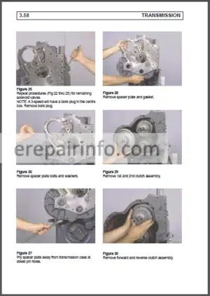
Main Gearbox
–SELECTOR RAILS AND FORKS
Introduction
Removauinstallation Of The Main Gearbox Selector Rails And Forks
Preliminary Steps
Removauinstallation Of The Selector Railsand Forks For 1St 2Nd 3Rd And 4Th Gears
B1329 And B1335Gearboxes Removal/Installation Of The Selector Rails And Forks For The Road Fl Eld Range
B1325 Gearbox Removal/Nstallation Of The Selector Rails And Forks For The Road Fl Eld Range
B1325 Gearbox Removal/Installation Of The Selector Rai Ls An D Forks For The Slow’crawler Range
B1325 -B1329 Input Gearboxes Control Lever Adjustment B1325 And B1329
Removal/Installation Of The Selector Rails And Forks For The B1335 Gearbox
Power Take Off Clutch Shaft Remcval?!Ns1Alla! Ion Of Theclutch Cont Rol And Clutch Guide Stops
Removal Of The Power Take Off Clutch Shaft
Removal Of The Power Take Off Clutch Shaft
Removal Of The Power Take Off Clutch Shaft
Reinstallation And Adjustment Of The Power Take Off Clutch Shaft
Adjustment Of Thebearingpreload
–B13.29 INPUT GEARBOX REVERSER – DOUBLER
Preliminary Steps
Removal Of Thereverser-Doubler Mechanism
Removal Of Thereverser-Doubler Mechanism
Installation Of The Reverser-Doubler Mechanism
Adjustments
Installation Of The Input Housing
Final Operations
-B13.25 INPUT HOUSING REVERSER – REDUCTION GEARBOX SLOW/CRAWLER RANGE
Preliminary Steps
Input Hou Si Ng Removal
Removauinstallation Of Thereverser Mechanism
Installation Of Parts On The Main Gearbox Housing
Input Housing Installation
Final Steps
–B1335 TRACTONIC INPUT HOUSING
Preamble
Breakdown
Description
Operation
Cab Controls
Operation
Safety
Clutch Adjustment
Synchro Forks Adjustment
Hydraulic Untt
Disconnection Between The Clutch Casing And The Gearboxhousing
General Removal
Disassembly-Reassembly- Clutch Adjustments
Disassembly-Reassembly-Intermediate Shaft Adjustments
–PRIMARY SHAFT
Introduction
Preliminary Steps
Primary Shaft Removal
Primary Shaft Installation
Bearing Preload Adjustment
Final Steps
–SECONDARY SHAFT
Preliminary Steps
Secondary Shaft RemCЛ/Al’installaticn
Mounting Distance Adjustment
Final Steps
Various Operations On The Secondary Shaft
–FRONT INTERMEDIATE SHAFT
Preamble
Preliminary Steps
Shaft Removauinstallation
Installation Of The Front Intermediate Shaft And Bearing Prelcading
Final Steps
-REAR INTERMEDIATE SHAFT AND REDUCTION GEAR DRIVE
Preamble
Preliminary Steps
Shaft Remo/Al/Installation
Installation Of The Front Intermediate Shaft And Bearing Preloading
Removauinstallation Ofthereduction Gear Train
Final Steps
–POWER TAKE OFF SHAFTS
Presentation
Controls
Specific Features Accordingtothetype Of Gearbox
Removauinstallation – General
Preliminary Steps
Removal Of Selector Rai Ls An D Forks
Rear Shaft Removauinstallation
Front Shaft Removauinstallation
Removauinstallation Ofthereduction Gear Train
Installation Of The Selector Rails And Forks
Adjustment Of Thepower Takeoff Levers
Final Steps
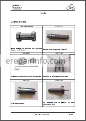
–TOOLS
Gearbox Tools
-LOW PRESSURE HYDRAULIC SYSTEM
–SPECIFICATIONS
Specifications
–PRESENTATION
Introduction
Operaton
Hydrauuc Coupling Tightening Torques
–CHECKS
Checks
–TOOLS
Hydrauuc System Tools
-REAR AXLE
–SPECIFICATIONS
General Specifications
–PRESENTATION
General
Centre Housing assembly
–ACCESS – REMOVAL/INSTALLATION OF THE HOUSING ASSY
Accessand Removal Of The Rear Axle Housing
Installation Of The Rear Axle Housing
–POWER TAKE OFF EXTENSION SHAFT
Removauinstallation Of The Po/Ver Take Off Shaft
–DIFFERENTIAL SHAFTS
Removauinstallation Of The Differential Shafts
–DIFFERENTIAL AND CROWNWHEEL
Removal/Installation Of The Differential And Thecrcwn Wheel
Final Steps
–TRUMPET HOUSINGS AND WHEEL SHAFTS
Removal/Installation Of Trumpet Housingsand Wheel Shafts
–DIFFERENTIAL LOCKING CONTROL
Removauinstallation Of The Differential Lock Internal Mechanism
External Control Adjustment
–TOOLS
Rear Axle Tools
-OIL BATH DISC BRAKES
–SPECIFICATIONS
Service Brakesand Handbrake
–SERVICE BRAKES – HANDBRAKE
General
Operation
Tightening Torques
Brake Removauinstallation
Brake Control Adjustment
–HYDROSTATIC CONTROL
Brake Fluid
Master Cyunders
Operaton
Pedal And Mcroswrtch Adjustmentvalues
Bleeding The Brake System
Master Cylinder Adjustment
–TOOLS
Service And Handbrake Tools
-4-WHEEL DRIVE UNIT
–4-WHEEL DRIVE UNIT
General
Operation
Safety Devices
Adjustment Values
4Wd Unit Removal
Spring Assembly Adjustment
Piston Stroke Adjustment
4Wd Unit Installation
Bearing Play Adjustment
Functional Check
Final Steps
–TOOLS
4Wd Unit Tools
-FRONT AXLE
FRONT AXLE SPECIFICATIONS
BEVEL GEAR DIFFERENTIAL
TIGHTENING TORQUES
DRIVE TRANSMISSION
SERVICING
PRELIMINARY DISASSEMBLY PRIOR TO MAINTENANCE
STEERING CYLINDERS AND LINK RODS
REMOVAL – INSTALLATION
Epicyclic reduction unit
Wheel hub
King pin
UNIVERSAL JOINT
DIFFERENTIAL
BEVEL GEAR AND CROWN GEAR
Bevel gear setting distance adjustment
Bevel gear preload adjustment
Gear backlash
Differential bearing preload
Reassembly
TOOLS
Special tools
Tools
-HYDRAULICS
Hydraulic System Specif Cations
Presentation Of The Various Circurts
Hydraulc System Diagram For 550 Series
Hydrauucsystemdiagramfor610-630-650Series
Schematic Diagram For TE Mis 610630-650Wrth Tra2Tonic
Schematic Diagram For Temis610-630650Wrthouttradtonic
Schematic Diagram For TEM Is 550 Without Tractonc
Sche Mat Ю Diagram For TE Mis 550 With Tractonc
-BRAKE VALVE
General
Type And Identification
Description
Brake Valve Float Diagram
Operation
Repair
Adjustmentof The Trailer Braking Pressure
-HYDRAULIC MANIFOLD
Circurt Diagram For The Hydraulic System
Pressureline
Operation
Type And Identification Of The Hydrauuc Manifold
Purpose Of The Hydraulic Manifold
Description
Safety Valve Characteristics
Repair
Tools
–AUXILIARY DISTRIBUTOR
Hydrauuccircuit Diagram
General
Description
The Auxiliary Distributor Flcw Diagram
Operation
Repair
Tools
–MAIN DISTRIBUTOR
Identification And Type Of The Main Distributor
Representation Of The Hydraulic Circuit
Operation Of The Hydraulic System
Description
Schematic Representation Of The Main Distributor
Operation
Tightening Torquesand Data
Repair
–MAIN DISTRIBUTOR (REXROTH SIGMA)
Hydrauuccircuit Diagram
Circurtlayout
Maindistributor (Rexroth Sigma)
Standard Representation
Description
Proportional Actuator
Distrirutor
Repair
Special Instructions
Designation
Description
–STEERING UNIT
Description
Disassembly
Disassembly Of The Safety Valve On Ospc
Disassembly Of The Pressure Relief Valve On Ospc
Disassembly Of The Pressure Relief Valve On Ospf
Ospc Steering UnГГ Assembly
Ospf Steering Unrt Assembly
Cleaning
Inspection And Replacement
Lubrication
Reassembly
Reassembly Of The Pressure Relief Valve
Safety Valve Reassembly
–VALVE (OLSA)
Description
Disassembly
Conversion
Cleaning
Inspection And Replacement
Lubrication
Reassembly
–TROUBLESHOOTING SHEET
Test Conditions
Flowpressureat The Auxiliary Distributor Outlets
Flow/Pressureat The Various Pump Out Lets
Flow/Pressureat The Steering Unr Inlet And
Pressureat The Steering Cyunder Inlet
–HYDRAUUC LIFT
Lift Arm Seal Replacement
Sensor Seal Replacement
Removal Of The Lift Housing
Removal Of The Uft Armsand Centrelever
Removal Of The Bar And Sensor Pot
Piston Sealsand Uner Bottom Seal
Lift Control Adjustment
Assistor Ram
-ELECTRICS
Wiring And General Lists
Diagrams And Functions
Harness Connections And Links
Cable Routing
Miscellaneous
Special Tools
-INSTRUMENT PANEL
GENERAL – FUNCTIONS PROVIDED
DESCRIPTION
WARNING LIGHTS ANDINSTRUMENTPANEL
TACHOMETER PANEL
ACCES TO BULBS
WARNING LIGHTS ANDINSTRUMENTPANEL
TACHOMETER PANEL
OPERATION
WARNING LIGHTS ANDINSTRUMENTPANEL
Red Alarm Functions And Associated Circuit Diagram
Orange Alarm Functions And Other Warning Lights
Display Of Engine Temperature And Fuel Gauge, With Associated Circuit Diagram
TACHOMETER PANEL
Analoguetachometer
Powertake Off Speed / Hourmeterand Speedometer
Associated Circuit Diagram
REMOVAL / INSTALLATION OF CONNECTORS
CONNECTION AND FUNCTIONS OF WIRES
WARNING LIGHTS ANDINSTRUMENTPANEL
TACHOMETER PANEL
PERSONAL NOTES
CONFIGURATION
PROCEDURE FOR CONFIGURING THE FORWARD SPEED
PERSONAL NOTES
-ELECTRONIC TRACTO CONTROL UNIT
General Arrangement
Control Panel
-TRACTONIC ELECTRONIC CONTROL UNIT
–GENERAL
General
–SENSORS, USER CONTROLS, WIRING
Sensors
Oil Pressure Swrtch
Temperature Cut-Out
Declutching Potentiometer
Clutch Control System Design
Installation Orientation Of Washers- Longitudinal Section
Potentiometer Upper Stop Adjustment
Potentiometer Lower Stop Adjustment
Tripler Unitcontrol
Tripler Speed Indicator Lights Management
Reverser Switch
Schedule Of Theposrtions Of Theclutchesand Slidinggears
For The Various Speeds
Instrument Panel Harness Wiring
Hydrauucunrt Harness Wiring
Hydraulic UnГT Components Test Methoo
Wiring Current Measurement In The Proportional Solenod Valves
Supply Voltage Check
Indicator Ughts Strip
Repair Of The Hydrauuc Unit Connector
Physical Location Of The Rems
–FUNCTIONS
Clutch Pedal Control
Automatic Programmed Clutch Engagement
Indicatorlights
–METADIAG APPLICATION FOR TEMIS TRACTONIC
Connection Of The Interface And Cables
Consultation Request
1Stoption
2Nd Option
3Rd Option
4Th Option
Sth Option
Cth Option
–TOOLS
Tractonic Ecu Tools
-INFOTRAC ON-BOARD COMPUTER
FUNCTIONS PROVIDED
DESCRIPTION OF THE COMPUTER
OPERATION
Partial and total events counter
Partial and total distance travelled
Partial and total area worked
Partial and total timeworked
Instantaneous surface worked per hour
Outside air temperature
Tool width program ming
Summary of functions and measurement ranges
REMOVAL/INSTALLATION OF THE UNIT
Removal of the bulbs
CONNECTION AND FUNCTIONS OF THE CONNECTOR WIRES CALIBRATION
Speed calibration procedure
Maintenance function
Personal notes
SENSORS
LAYOUT
PERSONAL NOTES
-CAB
–REMOVAL OF THE COMPLETE CAB
Preliminary Operations – Safety
Raising Thecabonly With Alifting Beam
–LIFTING THE CAB FOR TEMIS X 4-CYLINDER MECHANICAL GEARBOX AND TCM
Lhside
Rhside
Additional Operationstobeperformed With:
Tce
Tractonc
Air Conditioning
-LIFTING THE CAB FOR TEMIS Z 6-CYLINDER TRACTONIC GEARBOX
Add Rtional Operations To Be Perform Ed With:
Mechanical Gearbox
TOOLS
What you get
You will receive PDF file with high-quality manual on your email immediately after the payment.


Reviews
There are no reviews yet.