


Factory Service Manual For Clark Forklift. Manual Contains Illustrations, Instructions, Diagrams For Step By Step Remove And Install, Assembly And Disassembly, Service, Inspection, Repair, Troubleshooting, Tune-Ups.
Format: PDF
Language: English
Pages: 222
Number: SM568 (december 1991)
Bookmarks: Yes
Searchable: Yes
Wiring Diagrams: Yes
Model
Clark Forklift
PWD25
PWD30
PWD36
HWD25
HWD30
HWD36
Contents
-PLANNED MAINTENANCE PROCEDURES
H.P.M. CHECK SHEET
Visual Inspection
Operational Tests
-LUBRICATION & PLANNED MAINTENANCE
Lubrication Specifications
Hydraulic System
Lubrication Chart Rider Models
Lubrication Chart Walkies Models
Optional Equipment
Miscellaneous Linkage
-BATTERY
Battery Handling
Battery Removal
Battery Vents
Battery Cleaning
Battery Maintenance
Battery Charging
Battery Electrolyte
Clean Battery Compartment
Install -Battery
Keeping Battery Records
-ELECTRIC MOTORS
Electric Motor Maintenance
Test For Motor Insulation Resistance To Ground
Brush And Commutator Inspection
Operating Conditions
Drive Motor
Pump Motor
Electrical Motor Maintenance General Procedures
Adjustment
Drive Motor Installation
Pump Motor Installation
-CONTACTORS
Replacement Of Contact Tips
Install New Tips
Check Operation
Forward & Reverse Contactor Assemblies
-CONTACTOR AND EV-T5 CONTROL PANELS
Control Panel Removal
Disconnect Panels
Control Card Removal & Installation
Replacement Control Card Data
Capacitors
Control Box Internal Wiring
-EV-T5 CONTROL
Description
Control Features
Maintenance
Troubleshooting
Trouble Shooting Notes
-CHECKING COMPONENTS AND CONTROL CARD ADJUSTMENTS
EV-T5 Card Adjustments And Input/Output Connections
EVT5 Component Identification
EV-T5 Internal Wiring
Checking Components
-SEQUENCE OF OPERATION
-EV-T5 FLOW CHART TROUBLE SHOOTING PROCEDURES
-DRIVE UNIT ASSEMBLY
Description
Removal
Disassembly
Cleaning & Inspection
Reassembly
Adjustment Specifications
Backlash
Installation
-DRIVE MOTOR BRAKES
Motor Brake Assembly
Motor Brake Inspection
Brake Installation
Brake Linkage Installation
Brake Switch
Brake Switch Adjustment
-COAST CONTROL
Coast Control Description
Coast Control Preparation
Coast Control Operational Check
Coast Control Operational Adjustment
-CASTER ASSEMBLY
Torque Specification
Caster Adjustment
-HYDRAULIC SYSTEM
Removal
Installation
Torque Specifications
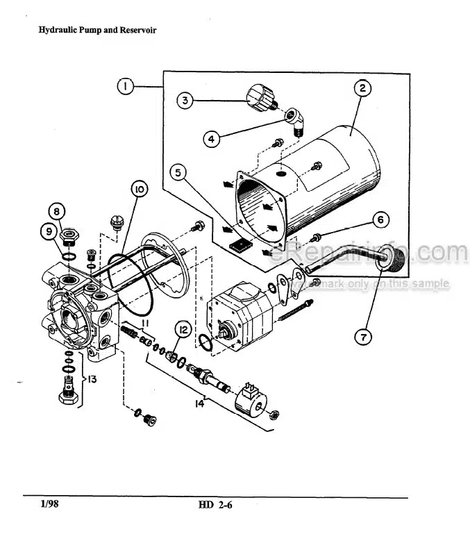
-HYDRAULIC UNIT
Assembly Of Hydraulic Unit
Specifications
-LIFT CYLINDER
Lift Cylinder Removal
Block Lift Frame
Disconnect Hoses
Disconnect Lift Cylinder
Disassembly
Inspection
Reassembly
Installation Specifications
-LIFT LINKAGE & LOAD WHEELS OPERATIONAL CHECK
Pull Rod Adjustment Check
Bushing Identification
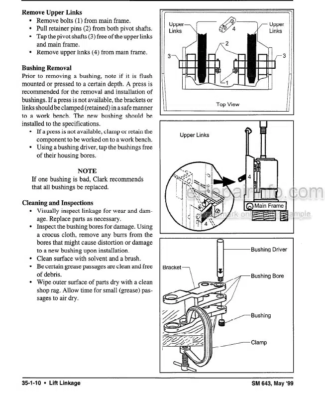
Lift Linkage Removal
Bushing Removal
Bushing Installation
Dual Load Wheels
Single Load Wheels
Lift Linkage Installation
Pallet Entry Skids
-BODY PARTS
Walkie Model Trucks
Rider Model Trucks
-TRUCK SPECIFICATIONS
Battery
Brake, Motor
Control (EV-TS Solid State Control)
Electrical
Hydraulic System
Truck Service Weights
Torque Specifications
-WIRING SCHEMATICS
IN-2222 (Early Model Trucks) Schematic (Early Model Trucks) Diagram
IN-24029 (Late Model Trucks) Schematic (Late Model Trucks) Diagram
What you get
You will receive PDF file with high-quality manual on your email immediately after the payment.


Reviews
There are no reviews yet.