


Factory Workshop Manual For Deutz Fahr Combine. Manual Contains Illustrations, Instructions, Diagrams For Step By Step Remove And Install, Assembly And Disassembly, Service, Inspection, Repair, Troubleshooting, Tune-Ups.
Format: PDF
Language: English
Pages: 640
Number: 307.1133.3.6 (October 2006)
Searchable: Yes
Wiring Diagrams: Yes
Hydraulic Diagrams: Yes
Model
Deutz Fahr Combine
5650H
5660HTS
5670H
6570HTS
5680H
5690HTS
Contents
-SAFETY INSTRUCTIONS
-GENERAL
Conversion Table
Tightening Torques, Bolting Classes
Lubricants
Sealing, Adhesives
Single-Component Adhesives
Maintenance And Inspection Schedule
Operating Fluids, Filling Levels And Oil Grades
Release List DEUTZ Lube Oil Quality Stage
Speeds
Tightening Torques For Adapter Sleeve Bearings
Check Tension Of Chain And Belt
Maintenance And Repair
Servicing And Maintenance
Special Tools
-ENGINE ASSEMBLY ENGINE PARTS, ENGINE CONTROL
Index Of Abbreviations
Safety Instructions
Technical Data DEUTZ Engine
Rating Plate / Serial Number
Bolt Tightening Torques
Description Of Engine
EMR, Electronic Engine Controller
Overview Power Supply EMR
Control Unit EMR, Gas Control Unit
Plug Assignments Of The EMR
Sensor And Transmitters Overview
Fuel System, Overview
Fuel Pump
Clean/Replace Fuel Pre-Filter, Filter Element; Bleeding Of Fuel System
Change Fuel Filter
Change Fuel Oil Leakage Pipe
Fuel Injection Valve, Injection Pipes Assembly, Disassembly
Testing And Setting Of Injectors Free From Leak-Off Fuel
Cooling Circuit, Overview
Draining / Filling Cooling System
Mounting Of The Coolant Temperature Transmitter
Replacement Of Thermostat
Mounting Of Coolant Pump
Maintenance And Inspection DEUTZ Engine, General
Maintenance Schedule
Air Filter
Coolant
Operating Media
Release List DEUTZ Lube Oil Quality Stage
Engine Oil Change
V-Belt Generator Tensioning/Replacement
Checking, Adjusting Valve Clearances
Adjustment Instruction For Valve Clearances
Determination Of Cylinder-Head Gasket
Mounting Of The Cylinder-Head
Tightening Of The Cylinder Head Screws Sequential Order
Special Tools
Charge Cooling
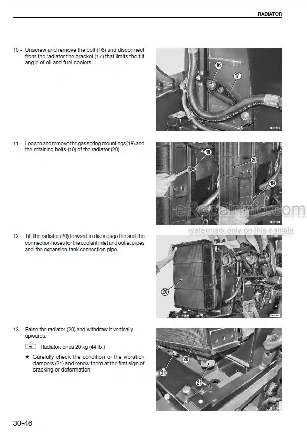
Cooling Fan Drive, Radiator
Exhauster Drive
Rotating Sieve Pan Drive
Driven Shaft Of Engine
Mounting Of Hydraulic Pumps
-ENGINE POWER TAKE-OFF
-FRONT AXLE, GEARBOX STEERING AXLE
-BELT DRIVE CLUTCHES GREASING EQUIPMENT
-HYDRAULIC
Safety Instructions
Circuit Symbols In The Hydraulic Circuit Diagram Conforming To ISO 1219
Circuit Diagram Working Hydraulics
Circuit Diagram Working Hydraulics In Case Of Balance
Layout Plan Working Hydraulics In Case Of Balance
Control Valve Block
Subplate For Control Valve Block: Flow Control Valve With Integral Pressure-Limiting Valve
Control Valve, Single-Acting
Control Valve, Double Acting
Pressure Accumulator Switching Valve With Pressure Sensor
EMR-D Control Valve
Balance
Working Hydraulic
Hydraulic Steering
Hydrostatic Ground Drive
-FEED PASSAGE
Feed Passage
Feed Passage Feed Passage Slip Clutch
Feed Passage, Stabilizing Shaft For Intake Chain
Feed Passage Clutch
Anti-Wrapping Device
Anti-Wrapping Device Between The Chain Sprockets
Reversing Device
Feed Passage Floating Frame, Tilt Adapter
-CABIN, DRIVER’S STAND
Driver’S Stand, Control Consoles
Commander Control 2000, EMR-D Control Panel
Driver’S Stand, Commander Stick, Control Consoles
Driver’S Stand, Steering Wheel
Cabin, Foot-Operated Controls, Parking Brake
Cabin, Operating Controls
Cabin, Operating Controls, Seats
Cabin Operating Controls
Cabin, Operating Controls, Emergency Exit
Cabin, Rear-View Mirrors
On-Board Computer (Optional)
Cabin Suspension
-ELECTRICAL SYSTEM
General, Safety Instructions
Index Of Abbreviations
Cable Colors And Color Coding For Connectors
Electrical System, Wiring Diagrams
System Overview Of Electrical System
Control Console, Overview
Operating Elements In Cabin Roof
Control Console, Switches And Lamps
Control Elements Commander Control 2000
Overview Wiring Diagram Electrical System
Fuse Assignment In Control Cabinet
Relay Assignment In Control Cabinet
Function Diode Arrays D1, D2, D3
Cable Harnesses, Connector Assemblies
Multiple Contact Strips In Control Cabinet
Multiple Contact Strips Under The Control Console
Connector Plug Configuration Foot Switch
Distributing Connector Engine Frame
Pin Configuration Actuator Connectors
Schematic Diagram Can Bus Commander Control 2000 With Combined
Instrument Gauge
Schematic Diagram Can Bus Commander Control 2000 With TERIS/TCS
Schematic Diagram Electrical Deflector Adjustment
Schematic Diagram Electrical Straw Guide Plate Adjustment
Schematic Diagram Electrical Sieve Adjustment Control
Wiring Diagram Can Bus System With Combined Instrument Gauge
Wiring Diagram Can Bus System With Commander Control
Function And Programming Of Can Modules
Connector Pin Assignment At Job Computer
Connector Pin Assignment Can Modules
-AIR CONDITION
-THRESHING MECHANISM
Threshing Section Clutch
Installation Of The Threshing Drum
Electrical Concave Adjustment
Concave Suspension, Disawner Plates
Installation Of The Rear Beater Drum
Drum Variator
Assembling The Variator Gear
Setting The Variator Adjusting Mechanism
Changing The Variator Belt
Dust Shields And Sealing At Threshing Mechanism
Drum Reduction Gear
Electrical Turbo Separator Clearance Adjustment
Installation Of Maize Threshing Concave
Threshing Drum – Maize Threshing, Weld Drum Bars With Rosettes
-CLEANING AGGREGATES
Straw Walker Drive
Setting The Drives
Mounting The Straw Walker Bearings
Mounting The Straw Walker Shafts And Straw Walkers
Mounting Of Straw Walker Guide Rakes
Sieve Pan Drive
Grain Pan With Removable Segments
Grain Pan, Sieve Box With Drive
Fan Variator
Fan – Airflow Guide System
Returns Elevator
Electrical Sieve Adjustment
-GRAIN ELEVATOR GRAIN TANK
Grain Elevator With Elevator Head
Elevator Head, Speed Monitoring
Elevator Head At Grain Tank Extension
Elevator Head With TCS (Grain Throughput Measurement)
Grain Tank Clutch
Grain Tank Unloading
Unloading System
Angular Gear Inside Of Tube Bend
Support For Grain Tank Tube, Interlock
Level Transmitter, Sensor For Grain Tank Cover
-CUTTING TABLE
-STRAW CHOPPER
What you get
You will receive PDF file with high-quality manual on your email immediately after the payment.


Reviews
There are no reviews yet.