


Factory Workshop Manual For Fendt F390GTA F395GTA F395GHA Tractors. Tons of illustrations, instructions, diagrams for step by step remove and install, assembly and disassembly, service, inspection, repair, troubleshooting, tune-ups.
Format: PDF
Language: English
Bookmarks: Yes
Wiring Diagrams: Yes
Model
Fendt F 390 GTA, F 395 GTA, F395 GHA
Contents
Lubricants, Sealants And Bonding Agents
List Of Models
Tightening Torques For Bolts
Fuels And Lubricants
Key To Pictorial Symbols
-Engine
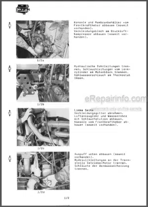
Engine, Removal And Fitting
Glow Starter (Cold Starter), Testing
Notes On Assembling The Engine-Oil Sump
– Gears
Drive Clutch, Removal And Fitting
Repair Kit For Clutch Master And Slave Cylinders, Fitting
Drive Clutch, Bleeding, Testing, Adjusting
PTO Clutch, Adjusting
Separating Tractor Between Engine And Clutch Housing
Double Clutch, Removal And Fitting
Double Clutch, Repairing
Clutch Mechanism In Clutch Housing, Removal And Fitting
Driving Shafts, Sealing
Side Selector Assembly And Housing Cover (Selector Gate Cover), Removal And Fitting, Dismantling And Assembly
Locking
Removal And Fitting, Dismantling
40 Km/H Gear,
30 Km/H Gear, And Assembly
40 Km/H Gear, And Assembly, Removal And Fitting, Dismantling
–Separating tractor between clutch housing and transmission
-540/750/1000 pto mechanism, removal and fitting, adjusting
Transmission, Dismantling And Assembly L/M/S Splitter
25/30/40 Km/H Overdrive
25/30 Km/H Overdrive
Super-Creeper Gear With L/M/S Splitter
–Separating Tractor Between Transmission And Rear Axle Housing
Pinion Shaft (Crown Gears) And Set Of Gearwheels Removal And Fitting
Front Wheel Drive
Shift Path Of 4-Wheel Drive Clutch, Testing
4-Wheel Drive Clutch Plates, Changing
Front Wheel Drive, Removal And Fitting, Dismantling And Assembly
Hydraulics
Electrics/Electronics, See Page 5/42
Forward And Backward Offset Of Front Wheel Drive, Measuring
Cardan Shaft, Removal And Fitting, Dismantling And Assembly
Rear PTO, Removal And Fitting
Differential Gears, Dismantling And Assembly
Differential Lock, Adjusting
Hydraulics, See Page 2/333
Electrics, Electronics, See Page 5/42
Diff Lock Slave Cylinder, Dismantling And Assembly
Differential, Removal And Fitting
Brakes
Wear On Rear Solid-Disc Brakes, Testing
Rear Solid-Disc Brakes, Adjusting
Rear Solid-Disc Brakes, Dismantling And Assembly
Rear Wheel Brake Cylinders, Removal And Fitting, Sealing With Repair Kit
Fixed-Caliper Brakes (Cardan Shaft Brakes), Removal And Fitting, Using Repair Kit
Main Brake Cylinder And Extra Valve, Testing For Internal Leaks
Main Brake Cylinder, Removal And Fitting, Adjusting, Sealing With Repair Kit
Brakes, Bleeding
Handbrake (Parking Brake), Adjusting
Handbrake (Parking Brake), Removal And Fitting
Brake Hydraulics Faults Table
Front PTO, Removal And Fitting
Clutch Plates, Changing, Dismantling And Assembly
Hydraulics
Electrics, Electronics
Clutch On Engine Side, Changing
Comfort Controls, Hydraulics
Position Of Components And Pressure Measurements Hydraulic Circuit Diagram
Comfort Controls, Electrics/Electronics, See Page 5/42
-Front Axle
Swivel Joint Between Front Axle Bracket And Axle Mounting, Sealing
Complete Front Axle, Removal And Fitting
Hydraulics
Electrics/Electronics
-Steering
Hydraulic Geared Pump, Removal And Fitting
Steering Unit, Removal And Fitting, Sealing
Priority Valve, Removal And Fitting, Dismantling/Cleaning
Steering Pillar, Removal And Fitting,Dismantling And Assembly
Steering Cylinders, Removal And Fitting,Sealing
Toe-In, Testing/Adjusting
Steering-Stop, Adjusting
Hydrostatic Steering, Testing
Max Pressure, Testing
Circulating Pressure, Testing
Steering Unit And Cylinders, Testing For Internal Leaks
Position Of Pressure Relief Valve In The Steering Unit
Hydrostatic Steering, Faults Table
-Electrics
Lights And Signalling
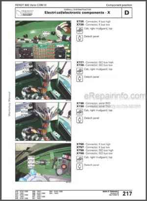
Position And Testing Of Electrical Components Position Of Line-Couplings
Position Of Earthing Points
Electrical Circuit Diagrams – Lighting, Signalling
Electronic Indicators And Comfort Controls Electrics And Electronics
Position And Testing Of Electrical And Electronic Components
Position Of Sensors
Electronic Control Box (E-Box) For Electronic Indicators, Encoding
Speed Indicator, Testing
Block Diagram – Electronic Indicators Block Diagrams – 4-Wheel Drive Comfort Controls And Diff Lock
Block Diagrams – Front PTO Comfort Controls Electrical Circuit Diagrams – Electronic Indicators And Comfort Controls
Faults Table – Electronic Indicators
Faults Code-Table – PTO Comfort Controls 4-Wheel Drive/Diff Lock
Faults Codes Table – Front PTO Comfort Controls
Functions – 4-Wheel Drive/Diff Locks Comfort Controls
Functions – Front PTO Comfort Controls
-Hydraulics
Hydraulic Geared Pump, Removal And Fitting, Dismantling And Assembly, Sealing
Hydraulic Oil Filter, Removal And Fitting
Control Valve For Lift-Controls Function Testing
Removal And Fitting
Magnets, Removal And Fitting
Pressure-Relief Valve In 1St And 2Nd Valve Units, Removal And Fitting, Cleaning
Additional Control Valves, Removal And Fitting Automatic Oil-Flow Connection, Testing, Removal And Fitting, Dismantling And Assembly
Position Of Non-Return Valve
Lifting Cylinders Of Electronically-Controlled Lifting-Gear Removal And Fitting, Dismantling And Assembly
Lifting Shaft Of Electronically-Controlled Lifting-Gear
Removal And Fitting, Sealing
Lifting-Gear, Removal And Fitting
Lifting-Gear, Adjusting And Testing
Hydraulic Circuit Diagrams
Sensor Pins, Removal And Fitting
Position And Testing Of Electrical And Electronic Epc Components, Pressureregulation And External Control
Epc Electrical Circuit Diagrams
Controls, Dismantling, Assembly, Testing
Electrical Circuit Diagram With Epc Test Values
Pressure Tests
Hydraulic Cylinders For Front Liftinggear, Removal And Fitting, Dismantling And Assembly
Faults Table – Electronically-Controlled Lifting-Gear And Working Hydraulics, Hydraulics
Faults Table – Electronically-Controlled Lifting-Gear, Electrics
Diagnostics – Electronically-Controlled Lifting-Gear, Fault-Code Indication
Shock-Load Stabiliser, Re-Coding
-Cab
Cab, Removal And Fitting
Cab Ventilation Fan, Removal And Fitting
Heater
Position Of Components
Power Supply, Testing
Testing Components When Fitted
Electric Circuit Diagram – Heater
Quantity Of Fuel, Measuring
Engine Fuse, Changing
Glow-Plug, Changing
Heater Unit, Removal And Fitting
Over-Heat Switch, Changing
Thermostat, Changing
Heating Unit, Dismantling And Assembly
Description Of Functions
Test Values For Control Unit, Cut-Off Relay And Rheostat
Technical Data
Cross-Section – D 3 L Heater
Faults Table
Operating The Time Switch
-Compressor
Compressor, Removal And Fitting, Sealing
Anti-Freeze Pump, Removal And Fitting, Sealing
Trailer Control Valve (For Single-Line System), Removal And Fitting, Sealing
Position, Testing And Adjustment Of Components
Compressor
Anti-Freeze Pump
Pressure Regulator
Pressure Gauge In Dashboard
Drainage Valve
Pressure Relief Valve
Trailer Control Valve (For Twin-Line System)
Trailer Control Valve (For Single-Line System)
Notes On Filling The Tyres
Testing The Compressor Unit – Summary
Function Diagram Of Compressor Unit
Faults Table
What you get
You will receive a PDF file with a high-quality manual on your email immediately after the payment.


Reviews
There are no reviews yet.