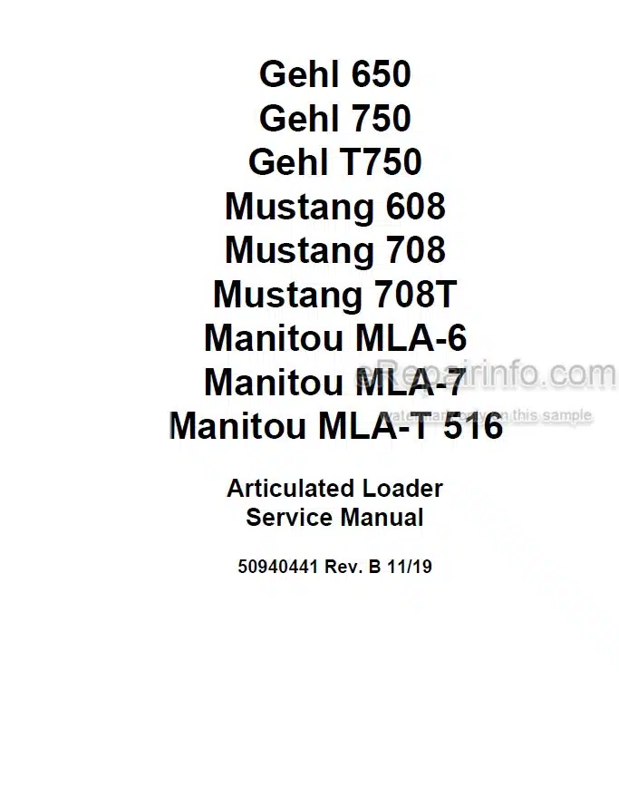
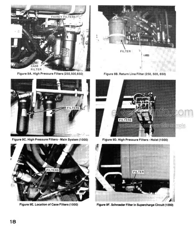
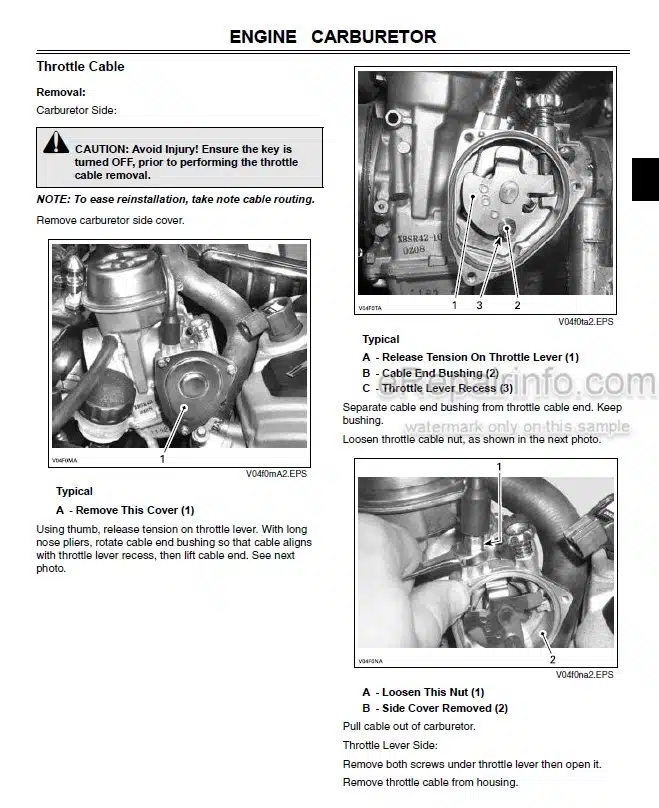
Factory Service Manual For Gehl, Mustang And Manitou Articulated Loader. Manual Contains Illustrations, Instructions, Diagrams For Step By Step Remove And Install, Assembly And Disassembly, Service, Inspection, Repair, Troubleshooting, Tune-Ups.
Format: PDF
Language: English
Pages: 654
Number: 50940441 (november 2019)
Bookmarks: Yes
Searchable: Yes
Wiring Diagrams: Yes
Hydraulic Diagrams: Yes
Model
Gehl, Mustang And Manitou Articulated Loader
Gehl 650
Gehl 750
Gehl T750
Mustang 608
Mustang 708
Mustang 708T
Manitou MLA-6
Manitou MLA-7
Manitou MLA-T516
Contents
-INTRODUCTION
Safety Symbol and Signal Words
Contents and Use of this Manual Machine Orientation
Proper Machine Use
Model/Serial Numbers
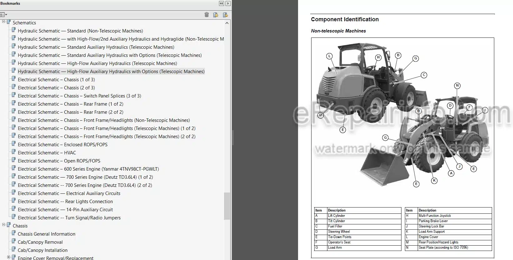
Component Identification
Fields of Application
Using Attachments
Fire Extinguisher
Manufacturer Information
Indicator and Operation Symbols
-SAFETY
Safety Symbol and Signal Words
Mandatory Safety Shutdown Procedure
Before Starting
During Operation
Provision for Stability/Avoiding Rollover and Tipover Accidents
Telescopic Machines
Articulated Loader Stability
Applications with Load-Handling Devices
Parking the Machine
Electrical Energy
Maintenance and Service Safety Practices
Battery Hazards
Fire Hazards
Additional Safety Equipment
Crystalline Silica Exposure
Transporting the Machine
Raising the Machine with a Crane
Loading and Transporting the Machine
Safety Decals
ANSI-Style and Common Safety Decal Locations
ISO-Style Safety Decal Locations
-INDICATORS AND CONTROLS
Multi-Function Display
Control Keypad
Switch Panel
Telescopic Machines Load/Level Indicators (Telescopic Machines)
Ignition Switch
Operator’s Seat/Armrest
Multi-Function Joystick
Parking Brake
Control Lever (Option)
Throttle Controls
Travel Controls
High/Low Travel Speed Selection
Constant Speed (Option)
Differential Lock
Engine Off Load Arm Lower
Hydraulics Transport Lock-out
Attachment Mounting
Auxiliary Hydraulic System
Hydraglide Button (Option)
Cooling Fan Rotation Reversing Button
Cab Heat and Air Conditioning (HVAC)
Work Lights Button
Load Arm Lights Button (Telescopic Machines Only)
Beacon (Option)
Windshield Wiper/Washer and Defrost
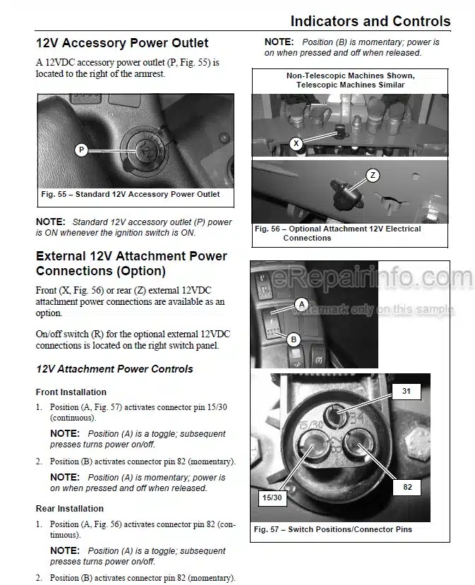
12V Accessory Power Outlet
External 12V Attachment Power Connections (Option)
Battery Disconnect Switch
-OPERATION
Operational Checks
Before Operation
Seat Belt
Dome Light
Starting the Engine
Engine Warm Up
Run-In Period
Stopping the Engine
Engine Stalling
Safety Interlock System (Hydraloc1)
Travel Drive Operation
Constant Speed Operation (Option)
Special Considerations for Telescopic Machines
Load Arm Operation
Load Arm Raise/Tilt Support (Non-Telescopic Machines Only)
Self-Leveling and Return-To Dig
Hydraglide Ride Control System (Option)
Hydraulics Transport Lock-Out Operation
Connecting/Disconnecting Attachments
Powering Attachments with Hydraulic Function
14-Pin Connector (Option)
Working with Buckets
Working with Pallet Forks
Diesel Particulate Filter (DPF) Regeneration Procedures
After Operation
Jump-Starting
Raising the Machine using a Crane
Towing
Loading and Transporting the Machine on a Transport Vehicle
-MAINTENANCE
Maintenance Schedule
Maintenance Interval
General Lubrication
Telescopic Load Arm Maintenance (Telescopic Machines Only)
LLMI Calibration (EU Telescopic Machines Only)
Engine Maintenance
DPF Service
Fuel System Maintenance
Hydraulic System Maintenance
Hydraulic Hose Maintenance
Planetary Axles
Brake Fluid Reservoir
Parking Brake Adjustment/Service
Wheels and Tires
Travel Motor Lubrication
Electrical System
HVAC/Air Conditioning Maintenance
Windshield Washer Reservoir
Long-Term Storage
Final Shutdown / Decommissioning
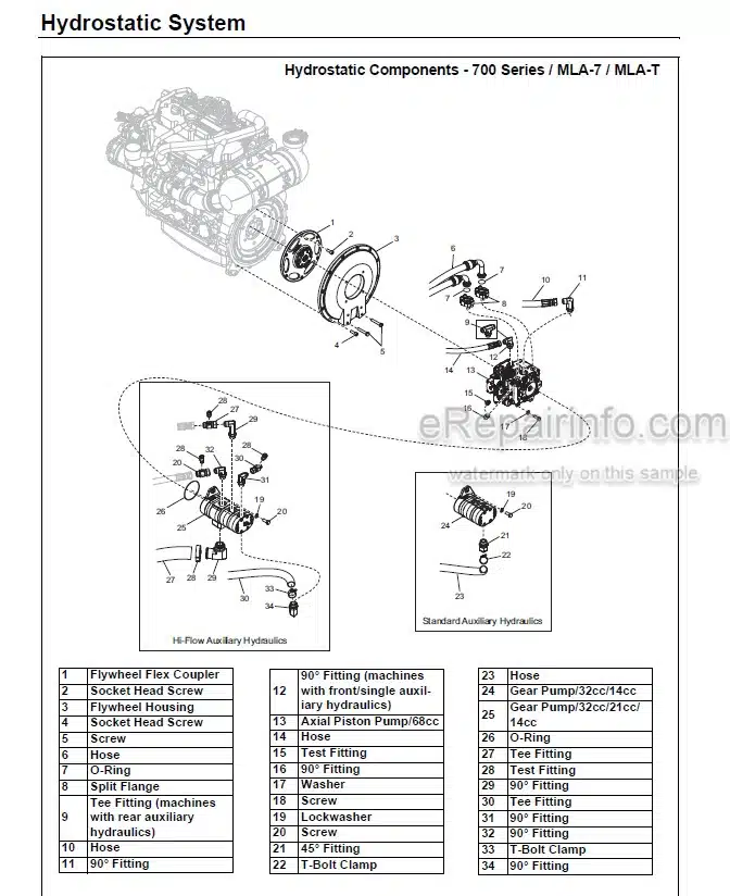
-HYDROSTATIC SYSTEM
Hydrostatic System General Information
Charge Pressure Test and Adjustment
Hydrostatic Pump Pressure Relief Valves
600 Series IMLA-6 Hydrostatic Pump Removal
Splined Coupler Removal/Installation
600 Series / MLA-6 Hydrostatic Pump Installation
700 Series IMLA-71MLA-T Hydrostatic Pump Removal
Splined Coupler Removal/Installation
700 Series I MLA-71 MLA-T Hydrostatic Pump Installation
Hydrostatic Pump Drive Coupling Removal and Installation
-DRIVE SYSTEM
Drive System General Information
Pump and Drive Motor Error Codes
Hydraulic Drive Motor
600 Series / MLA-6 Hydraulic Motor Removal
600 Series / MLA-6 Hydraulic Motor Installation
700 Series / MLA-7 / MLA-T Hydraulic Motor Removal
700 Series / MLA-71 MLA-T Hydraulic Motor Installation
Brake/Inching Pedal Calibration
Bleeding the Brake System
Brake/lnching Pedal Electrical
Throttle Pedal Electrical
Hand Throttle Electrical
Transmission Control Unit (TCU)/ Drive Controller
-HYDRAULIC SYSTEM
Hydraulic System General Information
General Hydraulic Service Notes
Hydraulic System Diagrams
Main Pressure Test and Adjustment
Control Valve
Non-Telescopic Machines Tilt/ Lift Cylinder Tests
Telescopic Machines Lift/Tilt Functional Description
Telescopic Machines TiIt/Lift/ Extension Cylinder Tests
Hydraulic Cylinder Disassembly/ Assembly
Hydraulic Solenoid Valves and Tests
Hydraglide
Solenoid Valve Disassembly/ Reassembly
Steering
Hydraulic System Troubleshooting
-HYDRAULIC SCHEMATICS
Hydraulic Shematic
-ELECTRICAL CONTROL SYSTEM
Electrical Control System General Information
Control Modules
CAN System Service/Computer Connection
Operation/Controller Area Network (CAN) Functional Organization
Accessories and Options Functional Detail
CAN/Control System Troubleshooting
-ELECTRICAL SYSTEM
Power Distribution
Start/Glow Relay Solenoid Test
Control Modules
J1939 Data Connector
Easy Manager
-WIRE HARNESS DIAGRAMS
Wire Harness Diagram
-SHEMATIC
Hydraulic Schematic
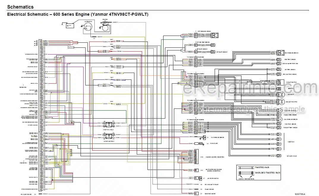
Electrical Schematic
-CHASSIS
Chassis General Information
Cab/Canopy Removal
Cab/Canopy Installation
Engine Cover Removal/Replacement
Articulation Joint
-TELESCOPIC LOAD ARM
Telescopic Load Arm Component Identification
Tilt Cylinder Removal/Installation
Inner Load Arm Hydraulic Tube and Hose Removal/Installation
Load Arm Slide Pad Service
Hose Support Removal
Hose Support Installation
Extension Indicator Potentiometer (Domestic Telescopic Machines)
-HVAC SYSTEM
Air Conditioning Refrigerant Recovery
Air Conditioning System Charging
700 Series I MLA-71 MLA-T Air Conditioning Compressor Removal
700 Series / MLA-7 / MLA-T Air Conditioning Compressor Installation
-600 SERIES IMLA-6 ENGINE
600 Series / MLA-6 Engine Removal
600 Series / MLA-6 Engine Installation
-700 SERIES / MLA-71 MLA-T ENGINE
700 Series / MLA-7 / MLA-T Engine Removal
700 Series / MLA-7 / MLA-T Engine Installation
-ENGINE COOLING SYSTEM
Engine Cooling System General Information
600 Series / MLA-6 Radiator Removal
600 Series / MLA-6 Radiator Installation
700 Series / MLA-7 / MLA-T Radiator Removal
700 Series / MLA-7 / MLA-T Radiator Installation
-TROUBLESHOOTING
Engine Troubleshooting
Indicator Lamp Troubleshooting
Seal and Hose Troubleshooting
Hydraulic System Troubleshooting
Hydrostatic Travel Drive System Troubleshooting
Electrical Troubleshooting
Error Codes
-SPECIFICATIONS
Fluids/Lubricants Types and Capacities
Payloads/Capacities
Dimensions
Weights
Coolant Compound Table
Wheels/Tires
Engine
Hydraulic System
Sound Power/Pressure Levels (Non-Telescopic Machines)
Sound Power/Pressure Levels (Telescopic Machines)
Vibration Levels
Common Materials and Densities
INDEX
TORQUE SPECIFICATIONS
What you get
You will receive PDF file with high-quality manual on your email immediately after the payment.


Reviews
There are no reviews yet.