


Factory Service Manual For Gehl Articulated Loader. Manual Contains Illustrations, Instructions, Diagrams For Step By Step Remove And Install, Assembly And Disassembly, Service, Inspection, Repair, Troubleshooting, Tune-Ups.
Format: PDF
Language: English
Pages: 360
Number: 918274 (december 2011)
Searchable: Yes
Wiring Diagrams: Yes
Hydraulic Diagrams: Yes
Model
Gehl Articulated Loader
AL140
AL240
AL340
Contents
— INTRODUCTION
— SAFETY
2-Post ROPS/FOPS Warning
Mandatory Safety Shutdown Procedure
Before Starting
During Operation
Service Safety Practices
Fire Hazards
Crystalline Silica Exposure
Safety Decals
— SPECIFICATIONS
Fluid Capacities/Lubricants
Dimensions – AL 300 and AL200 Series
Dimensions – AL 100 Series
SAE (Domestic) Weights and Capacities
AL 100 and AL 300 Series
ISO (EU) Weights and Capacities
AL 100, AL 200 and AL 300 Series
Engine
Hydraulics
Electrical System
Sound Levels
Wheels
Maximum Slopes of Operation
Wheel/Tire Sets
FOPS
Crane Lifting Chain Lengths
Vibration Levels
Vibration Information
— MAINTENANCE
Maintenance Schedule
Engine Maintenance
Fuel System
Checking and Adjusting V-belt Tension
Hydraulic System Maintenance
Planetary Axles
Lubrication
Electrical System
Storing the Loader
Maintenance Log
— OPERATION
Operation Safety
Controls and Switches
Instrument Panel and Indicators
Cab Controls (Cab only)
Warning Indicators
Operator’s Seat and Ignition Switch
Steering Column
Hand Throttle (AL300 Series only)
Lift Arm Down-Stop (AL200/300 Series)
Boom and Bucket Lock (AL100 Series)
— CHASSIS
Tilting the Platform
Lowering the Platform
Repairing or Replacing Platform Switch
Hood Removal
Hood Installation
Center/Steering Bearing Removal
Center/Steering Bearing Installation
Lift Arm Removal
Lift Arm Installation
Attachment Plate Removal
Attachment Plate Installation
— ENGINE
Engine Removal
Engine Installation
Drive Coupling Removal
Drive Coupling Installation
Starter Removal
Starter Installation
— COOLING SYSTEM
Radiator/Oil Cooler Removal
Radiator/Oil Cooler Installation
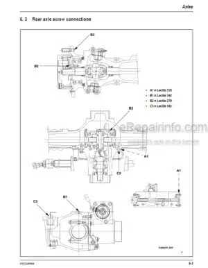
— AXLES
Service Brake Adjustment
Front Axle Removal
Front Axle Installation
Rear Axle Removal
Rear Axle Installation
— HYDRAULICS
Work Hydraulics Troubleshooting
Hydrostatic Drive System
Hydraulics Troubleshooting Diagnostic Flow Charts
Drive System Components
Charge Pump/Pilot Pressure Tests
Drive Pressure Tests
Work System Pressure Tests
Work Cylinder Leakage Test
2-Spool Control Valve Removal
3-Spool Control Valve Removal
2-Spool Control Valve Installation
3-Spool Control Valve Installation
Lift/Tilt Lock, Power-A-Tach® System and Auxiliary Hydraulics Valve Locations
Lift Cylinder Removal
Lift Cylinder Installation
Tilt Cylinder Removal
Tilt Cylinder Installation
Steering Cylinder Removal
Steering Cylinder Installation
Hydraulic Cylinder Disassembly/Assembly
Gear/Work Hydraulic Pump Removal
Gear/Work Hydraulic Pump Installation
Piston/Drive Hydraulic Pump Removal
Piston/Drive Hydraulic Pump Installation
Hydrostatic Motor Removal
Hydrostatic Motor Installation
Steering Control Valve Removal
Steering Control Valve Installation
Raising Machine for Drive System Troubleshooting
AL100 Series Hydraulic Schematic
— ELECTRICAL SYSTEM
Battery Removal
Battery Installation
Machine Controller
AL100 Series Complete Electrical Schematic
AL100 Series Standard Steering Column Electrical Schematic
AL100 Series Deluxe Steering Column Electrical Schematic (SN 11257 and Up)
AL100 Series Chassis Electrical Schematic (SN 11257 and Up)
AL100 Series Engine Electrical Schematic (SN 11257 and Up)
AL100 Series Road Homologation Electrical Schematic (SN 11257 and Up)
AL200 Series Complete Electrical Schematic – With Standard Steering Column
AL200 Series Standard Steering Column Electrical Schematic (SN 21244 and Up)
AL200 Series Deluxe Steering Column Electrical Schematic (SN 21244 and Up)
AL200 Series Chassis Electrical Schematic (SN 21244 and Up)
AL200 Series Engine and 4-Post ROPS Electrical Schematic (SN 21244 and Up)
AL200 Series Road Homologation Electrical Schematic (SN 21244 and Up)
AL100 and 200 Series Complete Electrical Schematic
— TROUBLESHOOTING
Engine
Indicator Lamps / Seals and Hoses
Hydraulic System
Hydrostatic Drive System
What you get
You will receive PDF file with high-quality manual on your email immediately after the payment.


Reviews
There are no reviews yet.