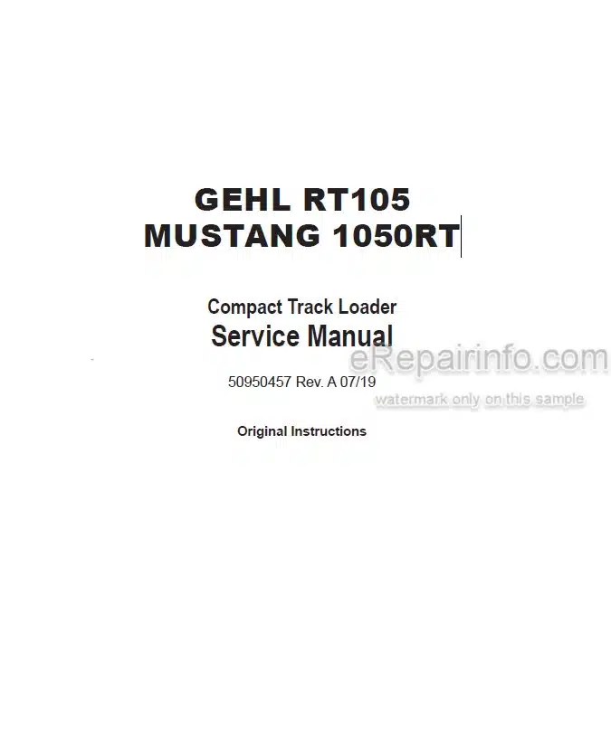
Factory Service Manual For Gehl And Mustang Compact Track Loader. Manual Contains Illustrations, Instructions, Diagrams For Step By Step Remove And Install, Assembly And Disassembly, Service, Inspection, Repair, Troubleshooting, Tune-Ups.
Format: PDF
Language: English
Pages: 353
Number: 50950457 (july 2019)
Searchable: Yes
Wiring Diagrams: Yes
Hydraulic Diagrams: Yes
Model
Gehl And Mustang Compact Track Loader
GEHL RT105
MUSTANG 1050RT
Contents
Introduction
Contents And Use Of This Manual
Machine Orientation
Machine Controls And Operation
Component Identification
Machine Model And Serial Number Locations
Indicator And Operation Symbols
Safety
Safety Symbol And Signal Words
Mandatory Safety Shutdown Procedure
Before Starting
During Operation
Applications With Load-Handling Devices
Parking The Machine
Electrical Energy
Maintenance And Service Safety Practices
Battery Hazards
Fire Hazards
Additional Safety Equipment
Crystalline Silica Exposure
Transporting The Machine
Lifting The Machine With A Crane
Loading And Transporting The Machine
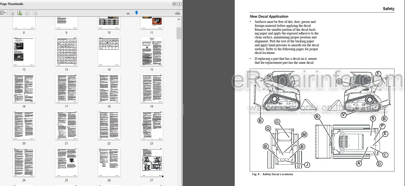
Safety Decals And Locations
Lifting The Machine Using A Crane
Loading And Transporting The Machine On A Transport Vehicle
Lubrication
Types Of Lubricants
Lubricant Capacities
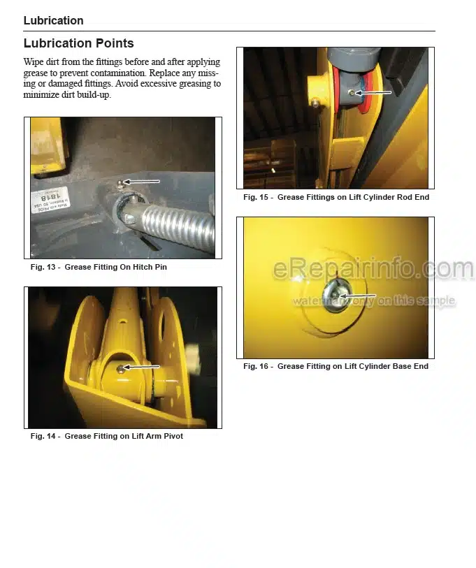
Lubrication Points
Lubrication Schedule Intervals
Filter Table
General Information
Hydraulic Oil Reservoir
Crankcase Oil
Grease Fitting Locations
Engine Cooling System
Maintenance
Maintenance Schedule
Engine Maintenance
Engine Access Cover
Engine Oil
Dpf Exhaust System Service
Fuel System Maintenance
Hydraulic System Maintenance
Hydraulic Hose Maintenance
Travel Motor Maintenance
Tracks
Electrical System
Windshield Washer Reservoir
Long-Tenn Storage
Final Shutdown / Decommissioning
Engine
General Information
Engine Access
Engine Maintenance
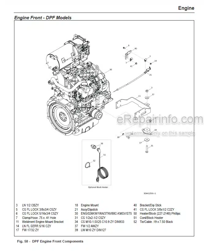
Engine Components
Adjustments
Engine Removal Installation
Radiator/Cooler Removal Installation
Air Filter Housing Removal/Lnstallation
Fan Shroud Removal Installation
Engine Fan Removalinstallation
Starter Removal Installation
Battery Removal/Lnstallation
Troubleshooting Guide
Engine Error Codes
Hydrostatic System
Introduction General Infoimation
General Hydraulic Service Notes
Hydraulic Oil Analysis
Theory Of Operation How It Works
Hydrostatic System Components
Hydrostatic Pump Removal/Installation
Hydrostatic Pump Drive Coupler Removal Installation
Bogie Wheels Removal/Installation
Track Removal Installation
Track Tension Cylinder Removal Installation
Sprocket Removal Installation
Front Idler Wheel Removal Installation
Travel Drive Motors
Tracks
Troubleshooting
Hydraulic System
Introduction General Information
General Hydraulic Service Notes
Hydraulic Oil Analysis
Hydraulic System Components
Main Pressure Test And Adjustment
Gear Pump Removal Installation
Control Valve Removal Installation
Lift Solenoid Valve Removal Installation
Solenoid Valve Test
Tilt Solenoid Valve Removal Installation
Brake Solenoid Valve Removal Installation
Tilt Cylinder Test
Lift Cylinder Removal Installation
Self-Leveling Valve Test
Self-Leveling Valve Removal Installation
Troubleshooting
Hydrostatic /Hydraulic Schematic
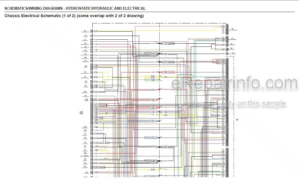
Chassis Electrical Schematic (1 Of 2) (Some Overlap With 2 Of 2 Drawing)
Chassis Electrical Schematic (2 Of 2) (Some Overlap With 1 Of 2 Drawing)
Rops Fops Electrical Schematic (1 Of 2) (Some Overlap With 2 Of 2 Drawing)
Rops Fops Electrical Schematic (2 Of 2) (Some Overlap With 1 Of 2 Drawing)
Stall Box Jumper Electrical Schematic
Chassis Hamess Wiling Diagram – Dpf Models
Rops/Fops Wiling Hamess Diagram – Dpf Models
Door Harness Wiring Diagram
Rear Wiper Hamess Diagram
Rops/Fops Wiling Hamess Diagram – Non-Dpf Models
Chassis Hamess Wiling Diagram – Non-Dpf Models
Rear Lights Hamess
Electrical Controls System
Electrical Control System General Infoimation
Control Modules
Can System Service/Computer Connection
Operation Controller Area Network (Can) Functional Organization
Can/Control System Troubleshooting
Indicator Lamp Troubleshooting
Electrical System
Battery
Introduction
Components
Power Distribution
Control Modules And Connectors
Component Tests
Light Bulb Replacement
Cab
Control Locations
Components
Control Adjustments
Rops Tops Cab
Tilt Rops/Fops
Ropstops/Cab Removal
Ropstops Installation
Restraint Bar Removal Installation
Hitch Removal/Lnstallation
Floor Plate Removal/Lnstallation
Crossmember Removal Installation
Pivot Tube Assembly Removal Installation
Pivot Tube Assembly Installation
Lift Tilt Control Removalinstallation
Electronic Foot Throttle Removal Installation
Seat Removal/Lnstallation
Control Handle Removal Installation
Heater Removal Installation
Programmed Display Removal Installation
Operator Presence Switch Removal Installation
Restraint Bar Switch Removal Installation
Lift Arm
Introduction
Notes
Lift Ann Components
Lift Ann Adjustments
Lift Aim Support
Lift Aim Removal
Lift Aim Installation
Specifications
Fluids Lubricants Types And Capacities
Dimensions
Payloads Capacities
Weights
Coolant Compound Table
Track Drive
Engine
Hydraulic System
Sound Power Pressure Levels
Vibration Levels
Torque Specifications
What you get
You will receive PDF file with high-quality manual on your email immediately after the payment.


Reviews
There are no reviews yet.