


Factory Service Manual For Mustang Compact Track Loader. Manual Contains Illustrations, Instructions, Diagrams For Step By Step Remove And Install, Assembly And Disassembly, Service, Inspection, Repair, Troubleshooting, Tune-Ups.
Format: PDF
Language: English
Pages: 316
Number: 50940649 (august 2020)
Bookmarks: Yes
Searchable: Yes
Wiring Diagrams: Yes
Hydraulic Diagrams: Yes
Model
Gehl, Mustang And Manitou Compact Track Loader
Gehl RT185
Gehl RT215
Gehl RT255
Mustang 1850RT
Mustang 2150RT
Mustang 2550RT
Manitou 1850RT
Manitou 2150RT
Manitou 2550RT
Contents
-SAFETY
Safety Symbol and Signal Words
Mandatory Safety Shutdown Procedure
Before Starting
During Operation
Applications with Load-Handling Devices
Parking the Machine
Electrical Energy
Maintenance and Service Safety Practices
Battery Hazards
Fire Hazards
Additional Safety Equipment
Crystalline Silica Exposure
Transporting the Machine
Lifting the Machine with a Crane
Loading and Transporting the Machine
Safety Decals
ANSI-Style Safety Decals
ISO-Style Safety Decals
Lifting the Machine using a Crane
Loading and Transporting the Machine on a Transport Vehicle
-INTRODUCTION
Contents and Use of this Manual
Machine Orientation
Component Identification
Machine Model and Serial Number Locations
ROPS/FOPS Certification Label
Indicator and Operation Symbols
Machine Controls and Operation
-MAINTENANCE
Maintenance Schedule
Engine Maintenance
DPF Service
Fuel System Maintenance
Hydraulic System Maintenance
Hydraulic Hose Maintenance
Travel Motor Maintenance
Track Maintenance
General Lubrication
Tilting ROPS/FOPS
Electrical System
Lighting
Long-Term Storage
Air Conditioning Maintenance
Windshield Washer Reservoir
Window Removal
Final Shutdown / Decommissioning
-MODELS RT255 AND 2550RT DEUTZ ENGINE
General Information
Engine Access
Engine Maintenance
Deutz Engine Removal/Installation
Fuel System Maintenance
Engine Troubleshooting
-MODELS RT215, RT185, 2100RT, AND 1850RT YANMAR ENGINE
General Information
Engine Access
Engine Maintenance
Yanmar Engine Removal/Installation
Fuel System Maintenance
Engine Troubleshooting
-HYDROSTATIC DRIVE SYSTEM
General Information
General Hydraulic Service Notes
Hydraulic Oil Analysis
Hydrostatic Drive Pump
Hydrostatic Pump Relief Valves
Travel Drive Troubleshooting
Neutral Centering Check/Adjustment
Straight Tracking Adjustment
Hydrostatic Pump Removal and Installation
Hydrostatic Pump Drive Coupling Removal and Installation
Travel Motors
Travel Drive High-Speed Troubleshooting
Tracks
Parking (SAHR) Brake Malfunctions
Hydrostatic Drive System Troubleshooting
-WORK HYDRAULICS
General Information
General Hydraulic Service Notes
Hydraulic Oil Analysis
Main Pressure Test and Adjustment
Hydraulic Gear Pump
Control Valve
Tilt/Lift Cylinder Service/Tests
Hydraulic Cylinder Disassembly/Assembly
Work Hydraulics Tests and Solenoid Valves
Hydraglide
Solenoid Valve Disassembly/ Reassembly
Work Hydraulics Troubleshooting
HYDRAULIC SCHEMATIC
-ELECTRICAL CONTROL SYSTEM
Electrical Control System General Information
Control Modules
CAN System Service/Computer Connection
Operation/Controller Area Network (CAN) Functional Organization
Accessories and Options Functional Detail
CAN/Control System Troubleshooting
Indicator Lamp Troubleshooting
-ELECTRICAL SYSTEM
Battery
Power Distribution
Glow Relay Solenoid Test
Power-A-Tach Relay Solenoid Test
Control Modules
Lighting
-WIRE HARNESS DIAGRAMS
Chassis Wire Harness Diagram -RT255 and 2550RT
Chassis Wire Harness Diagram -RT185, RT215,1850RT, and 2150RT
Deutz Engine Wire Harness Diagram – RT255 and 2550RT
Yanmar interim Tier 4 Engine Wire Harness Diagram – RT185, RT215,1850RT, and 2150RT
Yanmar Tier 4 Engine Wire Harness Diagram – RT185, RT215,1850RT, and 2150RT
ROPS/FOPS (Cab) Wire Harness
Operator’s Seat Wire Harness Diagram)
Rear Door Wire Harness Diagram)
14-Pin Connector Wire Harness Diagram)
-ELECTRICAL SCHEMATICS
Electrical Schematic
-LIFT ARM
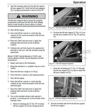
Lift Arm Support
Lift Arm Alignment Stops
Tilt Stop Adjustment
Lift Arm Removal
Lift Arm Installation
-ROPS/FOPS/CAB
Tilting ROPS/FOPS
ROPS/FOPS Removal
ROPS/FOPS Installation
-HVAC SYSTEM
Air Conditioning Refrigerant Recovery
Air Conditioning System Charging
INDEX
-SPECIFICATIONS
Fluids/Lubricants Types and Capacities
Dimensions
Payloads/Capacities
Weights
Track Drive
Coolant Compound Table
Engine
Hydraulic System
Electrical System
Sound Power/Pressure Levels
What you get
You will receive PDF file with high-quality manual on your email immediately after the payment.


Reviews
There are no reviews yet.