


Factory Service Manual For Gehl Skid Steer Loader. Manual Contains Illustrations, Instructions, Diagrams For Step By Step Remove And Install, Assembly And Disassembly, Service, Inspection, Repair, Troubleshooting, Tune-Ups.
Format: PDF
Language: English
Pages: 198
Number: 907846 (july 2000)
Searchable: Yes
Wiring Diagrams: Yes
Hydraulic Diagrams: Yes
Model
Gehl Skid Loader
SL5635
SL6635
Series II
Contents
-SPECIFICATIONS
Specifications
Tire Options
Buckets and Capacities
General Specifications
-SAFETY
General Information
Signal Words
Additional Safety Re minders
Mandatory Safety Shutdown Procedure
Liftarm Support Device
Liftarm Support Device Engagement
Liftarm Support Device Disengagement
Rollover Protective Structure (ROPS) – Raising
Rollover Protective Structure (ROPS) – Lowering
Relieving Hydraulic Pressure
Loader Raising Procedure
Loader Lowering Procedure
-LUBRICATION
General Information
Hydraulic Oil Reservoir
Crank case Oil
Chaincases
Grease Fitting Locations
-MAINFRAME
Introduction
Engine Access Cover Removal and Installation
Roll over Protective Structure (ROPS) Removal and Installation
Seat Removal and Installation
Seat Slide Replacement
Roll over Protective Structure (ROPS) Rear Window Removal and Installation
Restraint Bar Removal and Installation
Gehl All-Tach™ Attachment Removal and Installation
Liftarm Removal and Installation
Liftarm Bushing Replacement
Liftarm Stop Installation and Adjustment
Control Cover Removal and Installation
Floor Cover Removal and Installation
Fuel Level Sender Removal and Installation
Rear Grille Removal and Installation
Crossmember Removal and Installation
-WHEEL DRIVES
Introduction
Drive Chain Adjustment
Drive Chain Removal and Installation
Axle Housing Assembly Removal and Installation
Axle and Wheel Bearing Disassembly and Assembly
Idler Sprocket and Bearing Removal and Installation
-CONTROLS
Introduction
Control Handle Removal and Installation
Control Handle Position Adjustment
Control Handle Tracking Adjustment Traction Controls
Left Control Handle Assembly – Single Speed Control Han dies
Left Control Handle Assembly – Two-Speed Control Han dies
Right Control Han die Assembly
Pivot Tube Removal and Installation – T-bar Hand/Foot and Dual Hand Controls
Neutral Centering Device Adjustment
Control Aim Assembly Removal and Installation
Lift/Tilt Control Removal and Installation
Lift/Tilt Control Adjustment
Auxiliary Hydraulics Cable Removal and Installation – T-bar and Dual Hand Controls
Auxiliary Hydraulics Cable Adjust merit – T-bar and Dual Hand Controls
Auxiliary Hydraulics Linear Actuator Adjustment
Auxiliary Hydraulics Linear Actuator Removal and Installation – Hand Foot Controls
Auxiliary Hydraulics Mechanical Cable Adjustment – Hand/foot Controls
Auxiliary Hydraulics Mechanical Cable Removal and Installation – Hand foot Controls
Hand Throttle Throttle Rod and Cable Removal and Installation – T-bar and Dual Hand Controls Foot Throttle Removal and Installation – T-bar and Dual Hand Controls
Hand Throttle and Throttle Cable Removal and Installation – Hand Foot Controls
Hand Throttle Adjustment – Hand/foot
Hand Throttle Tension Adjustment
Foot Throttle Adjustment – T-bar and Dual Hand Controls
-HYDROSTATIC SYSTEM
Introduction
Trouble shooting Guide
Case Drain Test
Charge Pres sure Test and Adjustment
Hydrostatic Pump Re lief Valves
Hydrostatic Pump Removal and Installation
Hydrostatic Pump Drive Coupling Removal and Installation
Drive Motor Removal and Installation
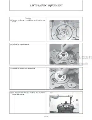
-HYDRAULIC SYSTEM
Introduction
Trouble shooting Guide
System Pres sure Test Control Valve and High Flow (DX models)
Tilt Cylinder Test
Self-Leveling Valve Test
Lift Cylinder Test
Solenoid Valve Test
Hydraulic Oil Filter Element Replacement
Tilt Cylinder Removal and Installation
Lift Cylinder Removal and Installation
Lift and Tilt Cylinder Disassembly and Assembly
Gear Pump Removal and Installation
Self-Leveling Valve Removal and Installation
Self-Leveling Valve Adjustment
Lift and Tilt Solenoid Valve – Removal and Installation
Lift and Tilt Solenoid Valve – Disassembly and Assembly
Control Valve Removal and Installation
High-Flow Man 1 fold Valve Removal and Installation (DX models)
High-Flow Man i fold Valve Disassembly and Assembly (DX models)
Pi lot Valve Removal and Installation – Hand/foot Controls
Hydraulic System Schematic, SL5635/6635 SX
Hydraulic System Schematic, SL5635/6635 DX
-ELECTRICAL SYSTEM
Description of Operation
Troubleshooting Guide
Glow Control Relay Operation
Re lay Test
Seat Switch Removal and Installation
Restraint Bar Switch Removal and Installation
Front Work Light Bulb Replacement
Rear Work Light Bulb Replacement
Electrical System Schematic
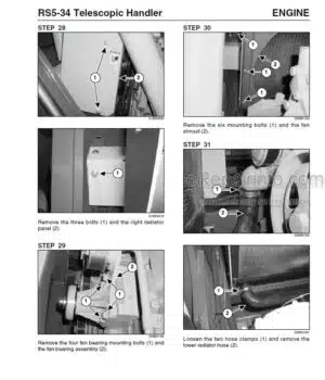
-ENGINE
Introduction
Trouble shooting Guide
Oil Filter Removal and Installation
Air Cleaner Assembly Removal and Installation
Air Filter Element Removal and Installation
Battery and Battery Tray Removal and Installation
Starter Removal and Installation
Exhaust Assembly Removal and Installation
Fan Belt Adjustment
Hydraulic Oil Cooler Removal and Installation
Fan Shroud Removal and Installation
Fan Shroud Adjustment
Engine Removal and Installation
What you get
You will receive PDF file with high-quality manual on your email immediately after the payment.


Reviews
There are no reviews yet.