


Factory Service Repair Manual For Hitachi EX120 Excavators. Tons of illustrations, instructions, diagrams for step by step remove and install, assembly and disassembly, service, inspection, repair, troubleshooting, tune-ups.
Format: PDF
Language: English
Pages: 984
Bookmarks: Yes
Searchable: Yes
Wiring Diagrams: Yes
Hydraulic Diagrams: Yes
Model
Hitachi EX120
Contents
- -HOW TO USE
–SECTION & GROUP CONTENTS
–INTRODUCTION
Introduction
Care of the Handling
Symbols
–FEATURES OF THIS MANUAL
Construction
Tab
Page
Contents
–SAFETY INFORMATIONS - -SPECIFICATION
–GENERAL SPECIFICATIONS
Dimensions
Weights and Ground Pressurers
Capability
Backhoe Attachments
Other Attachments
Working Ranges
Lifting Capacities
–COMPONENTS SPECIFICATIONS
Engine
Main Pump
Pilot Pump
Control Valve
Swing Motor
Travel Motor
Center Joint
Pilot Valve (for Travel)
Pilot Valve (for Swing, Boom, Arm, Bucket)
Control Neutralizer Valve
Sockless Valve
Accumulator
Hydraulic Tank
Suction Filter
Full-Flow Filter
Air Breezer
Bypass Check Valve
Pilot Filter
Oil Cooler
Restriction Valve
Solenoid Valve
Mode Selection Cylinder Boom Cylinder
Arm Cylinder
Bucket Cylinder
–TORQUE REFERENCE
–OTHERS
Maintenance Intervals
–CONVERSION TABLE - -GENERAL
–INTRODUCTION
–CONSTRUCTION
–HYDRAULIC SYSTEM
Hydraulic System
Main Hydraulic Circuit
Pilot Hydraulic Circuit - -ELECTRIC SYSTEM
Main Circuit
Control System
Monitor System
–MAINTENANCE
Removal & Installation
Maintenance
Name Plate - -SUPERSTRUCTURE
Main Frame & Counter-Weight
Engine
Hydraulic Oil Tank
Fuel Tank
Swing Device
Electric Parts
Cab Heater
Engine Control Lever
Main Piping
Oil Cooler Piping
Cover
Pump Device
Control Box
Cab Group
Pilot Piping
Control Lever
–HYDRAULIC PUMP DEVICE
O/P, Hydraulic Pump
D/A, Main Pump
–CONTROL VALVE
O/P, CV-22M Control Valve
D/A, CV-22M Control Valve
–SWING DEVICE
O/P, Swing Motor
D/A, Swing Motor
D/A, Swing Reduction Device
–PILOT VALVE
O/P, Pilot Valve
D/A, HV Type Pilot Valve (Front-End Attachment)
D/A, HV Type Pilot Valve (Travel)
–CONTROL NEUTRALIZER VALVE
O/P, Control Neutralizer Valve
D/A, Disassembly & Assembly
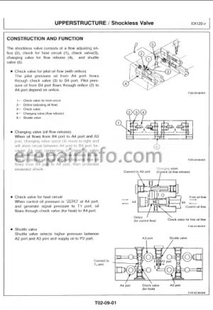
–SHOCKLESS VALVE
O/P, Shockless Valve
D/A, Shockless Valve
–ACCUMULATOR
O/P, Accumulator
–SOLENOID VALVE
O/P, Solenoid Valve
D/A, Solenoid Valve
–MODE SLECTION CYLINDER
D/A , Mode Selection Cylinder - -UNDERCARRIGE
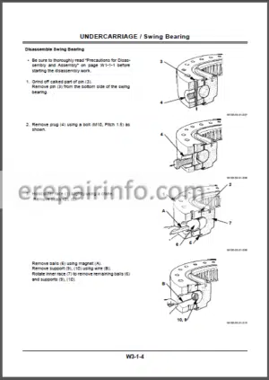
–UNDERCARRIAGE
Track Frame
Swing Bearing
Travel Device & Piping
Front Idler
Adjuster
Upper Roller & Lower Roller
Track Link
Center Joint
–TRAVEL DEVICE
O/P, Travel Motor
D/A, Travel Motor
D/A, Travel Device
–CENTER JOINT
O/P, Center Joint
D/A, Center Joint - -FRONT-END ATTACHMENTS
–FRONT-END ATTACHMENT
Boom Assembly
Arm Assembly
Bucket Assembly
Front Pipings
–HYDRAULIC CYLINDER
Operational Principle
Disassembly & Assembly
–PIN & BUSHING
Specifications
–POINT & SIDE CUTTER
Maintenance
–OUTLINE
–MAIN HYDRAULIC CIRCUIT
Suction Circuit and Delivery Circuit
Return Circuit
Drain Circuit
–PILOT CIRCUIT
Suction Delivery and Return Circuit
Accumulator
Control neutralizer Valve
Pump Displacement Control Circuit
Relief Pressure Change Circuit
Switch Valve Circuit
Swing Parking Brake Circuit
Heat-Run Circuit
–SINGLE OPERATION
Boom Raise Circuit Operation
Boom Lower Circuit Operation
Arm Roll-In Circuit Operation
Arm Roll-Out Circuit Operation
Bucket Circuit Operation
Swing Circuit Operatrion
Swing Operation
Travel Circuit Operation
Travel Forward and Reverse Operation
–COMBINED OPERATION
Outline
Combined Swing and Boom Operation
Combined Swing and Arm Operation
Combined Swing and Bucket Operation
Combined Swing, Boom, Arm and Bucket Operation
Combined Swing and Travel Operatrion
Combined Boom and Travel Operation
Combined Arm and Travel Operation
Combined Bucket and Travel Operation
–EXTRA CONTROL CIRCUIT
Outline
Single Operation
Combined Extra and Arm Roll-In Operation
Combined Extra and Arm Roll-Out Operation - -ELECTRICAL SYSTEM
–SAFETY PRECAUTIONS
Safety Precautions
–SPECIFICATiONS
Battery
Starter
Safety Relay
Alternator
Regulator
Head Light
Wiper Motor
Speaker
Fuse
–CONSTRUCTION & FUNCTION
Construction of Electrical System
Monitor
Control (E-P Control) System
Engine Reverse Rotation Preventive Device
Function of Sensor and Relays
–CIRCUIT OPERATIONS
Characteristics of Electrical Circuit
Electrical Circuit
Battery Circuit
Preheat Circuit
Starting Circuit
Charging Circuit
Safety Circuit
Engine Emergency Stop Circuit
Accessory Circuit
Gauge Panel Circuit
Control Circuit
–MAINTENANCE
Replacing Panel Gauge Parts
Assembly & Adjustment of Auto-Idle Device - -TROUBLESHOOTING
–INTRODUCTION
General Information
Notes on Performance Measurement
–DIAGNOSE MALFUNCTIONS
Malfunctions Phenomena
Hydraulic System
Electric System
–EXCAVATOR PERFORMANCE TEST
Introduction
Engine Performance Measurement
Travel Performance Measurement
Swing Performance Measurement
Front-end Attachment
Control Lever Performance Measurement - -COMPONENTS PERFORMANCE STANDARD
Introduction
Pilot Relief Valve
Main Relief Valve
Overload Relief Valve
Swing Overload Relief Valve
Travel Crossover Relief Valve
Main Hydraulic Pump
–ELECTRICAL SYSTEM TEST
Common Circuit Test
Articles Necessary for Electric Circuit Test
Measurement Procedure
Measurement Standard - -ENGINE
–GENERAL INFORMATION
General Repair Instructions
Notes on the Format of Engine Section
Main Data & Specifications
Design Features & General Outline
Tightening Torque Specifications
Anglular Nut & Bolt Tightening Method
Major Parts Fixing Nuts & Bolts
Identifications
–MAINTENANCE
Lubricating System
Fuel System
Cooling System
Valve Clearance Adjustment
Injection Timing
Compression Pressure Measurement
Turbocharger Inspection
Engine Repair Kit
Recommended Lubricants
Engine Oil Viscosity Chart
–ENGINE DISASSEMBLY
External Parts
Major Components
Rocker Arm & Rocker Arm Shaft
Cylinder Head
Piston & Connecting Rod
–INSPECTION & REPAIR
Cylinder Head
Valve Guide
Valve Spring
Tappet
Push Rod
Rocker Arm Shaft & Rocker Arm
Idler Gear & Idler Gear Shaft
Cam Shaft
Cylinder Body & Liner
Piston & Piston Ring
Piston Pin
Connecting Rod
Crankshaft
Fly Wheel & Fly Wheel Housing
Timing Gear Case Cover
–ENGINE ASSEMBLY
Piston & Connecting Rod
Cylinder Head
Rocker Arm & Rocker Arm Shaft
Major Components
External Parts
Engine Tuning Operation
Engine Section View
–LUBRICATING SYSTEM
General Description
Oil Pump
Main Oil Pump
Oil Cooler - -COOLING SYSTEM
General Description
Water Pump
Thermostat
–FUEL SYSTEM
General Description
Fuel Filter
Injection Nozzle
–TURBO CHARGER
General Description
Identification
Roter Shaft Play Inspection
–ENGINE ELECTRICALS
Starter Motor
Alternator
–TROUBLESHOOTING
Hard Starting
Unstable Low Idling
Insufficient Power
Excessive Fuel Consumption
Overheating
White Exhaust Smoke
Darkish Exhaust Smoke
Not Rising Oil Pressure
Abnormal Engine Noise
–SPECIAL TOOL LIST
What you get
You will receive PDF file with high-quality manual on your email immediately after the payment.


Reviews
There are no reviews yet.