


Factory Service Repair Manual For Hitachi Hitachi EX33Mu 58Mu Excavators. Tons of illustrations, instructions, diagrams for step by step remove and install, assembly and disassembly, service, inspection, repair, troubleshooting, tune-ups.
Format: PDF
Language: English
Pages: 789
Bookmarks: Yes
Searchable: No
Number:
Wiring Diagrams: No
Hydraulic Diagrams: Yes
Model
Hitachi EX33Mu, 58Mu
Contents
Workshop Manual
- INTRODUCTION
SAFETY - -GENERAL INFORMATION
–PRECAUTIONS FOR DISASSEMBLING AND ASSEMBLING
Precautions for Disassembling and Assembling
Maintenance Standard Terminology
–TIGHTENING
Tightening Torque Specifications
Torque Chart
Piping Joint - -UPPERSTRUCTURE
–CANOPY
Remove and Install Canopy
–COUNTERWEIGHT
Remove and Install Counterweight
Group 03-Pump Device
Remove and Install Pump Device
Disassemble and Assemble Pump Device (33Mu)
Disassemble and Assemble Pump Device (58Mu)
Maintenance Standard
–CONTROL VALVE
Remove and Install Control Valve
Disassemble and Assemble Control Valve
–SWING DEVICE
Remove and Install Swing Device
Disassemble and Assemble Swing Reduction Gear (33Mu)
Disassemble and Assemble Swing Reduction Gear (58Mu)
Disassemble and Assemble Swing Motor (33Mu)
Disassemble and Assemble Swing Motor (58Mu)
Disassemble and Assemble Parking Brake Switch Valve
Maintenance Standard
–PILOT VALVE
Remove and Install Front Pilot Valve
Remove and Install Swing Pilot Valve
Disassemble Front Pilot Valve
Assemble Front Pilot Valve
Disassemble Swing Pilot Valve
Assemble Swing Pilot Valve
–SOLENOID VALVE
Disassemble and Assemble Auto
Boom-Stop Solenoid Valve
Disassemble and Assemble
Pilot Control Shut-Off
LeverTravel Speed Change
Solenoid Valve - -UNDERCARRIAGE
–SWLNG BEARING
Remove and Install Swing Bearing
–TRAVEL DEVICE
Remove and Install Travel Device
Disassemble and Assemble Travel Device (33Mu)
Disassemble and Assemble Travel Device (58Mu)
–CENTER JOINT
Remove and Install Center Joint
Disassemble Center Joint
Assemble Center Joint
–TRACK ADJUSTER
Remove and Install Track Adjuster
–FRONT IDLER
Remove and Install Front Idler
Maintenance Standards
–UPPER AND LOWER ROLLERS
Remove and Install Upper Roller
Remove and Install Lower Roller
Maintenance Standards
–TRACK
Remove and Install Rubber Crawler
Maintenance Standards - -FRONT ATTACHMENT
— FRONT ATTACHMENT
Remove and Install
Front Attachment
Maintenance Standards
— CYLINDER
Remove and Install Cylinders
Disassemble Cylinders
Assemble Cylinders
Tightening Torque Specifications
Maintenance Standards - -ENGINE 33MU
–SAFETY INSTRUCTIONS
–SPECIFICATIONS
–PERFORMANCE CURVES
–DIMENSIONS
–MECHANISM
FEATURE
—ENGINE BODY
Cylinder Block
Cylinder Head
Crankshaft
Piston And Piston Rings
Connecting Rod
Camshaft
Flywheel
Rocker Arm
—LU8RICATING SYSTEM
General
Oil Pump
Relief Valve
Oil Filter Cartridge
Oil Pressure Switch
—COOLING SYSTEM
General
Waterpump
Thermostat
Radiator
Radiator Cap
—INTAKE/EXHAUST SYSTEM
Air Cleaner
Muffler
—FUEL SYSTEM
General
Injection Pump
Injection Nozzle
Fuel Filter
Fuel Lift Pump
Governor
—ELECTRICAL SYSTEM
Charging System
–DISASSEMBLING AND SERVICING
—GENERAL
Engine Identification
General Precautions
Tightening Torques
Troubleshooting
Servicing Specifications
Maintenance Check List
Check And Maintenance
Special Tools
—ENGINE BODY
Checking And Adjusting
Disassembling And Assembling
Draining Water And Oil
External Compornents
Cylinder Head And Valves
Gear Case
Piston And Connecting Rod
Flywheel And Crankshaft
Servicing
Cylindfrhead
Timing Gear And Camshaft
Piston And Connecting Rod
Crankshaft
Cylinder Bore
—LUBRICATING SYSTEM
Checking
Servicing
Oilpump
—COOLING SYSTEM
Checking
Fan Belt
Radiator
Disassembling And Assembling
—FUEL SYSTEM
Checking And Adjusting
Injection Pump
Injection Nozzle
Disassembling And Assembling
Injection Pump
Injection Nozzle
—ELECTRICAL SYSTEM
Checking
Starter
Glowplug
Alternator And Regulator
Disassembling And Assembling
Starter
Alternator
Servicing
Starter
Alternator - -ENGINE 58MU
— GENERAL INFORMATION
General Repair Instructions
Notes On The Format Of This Manual
Appearance
Main Data And Specifications
Tightening Torque Specifications Angular Nut And Bolt Tightening Method
Tightening Torque On Major Components
Gasket Location
Maintenance
Recommended Lubricating Oil
— ENGINE
Disassembly
Inspection And Repair
Reassembly
— LUBRICATING SYSTEM
Lubricating Oil Circulation System Diagram
Oil Pump
— COOLING SYTEM
Cooling Water Circulation System Diagram
Waterpump
Thermostat
— FUEL SYSTEM
Fuel Circulation System Diagram Governor
Nozzle Holder Assembly
— TROUBLESHOOTING
— SPECIAL TOOLS
— CONVERSION TABLE LENGTH
Area
Volume
Mass
Pressure
Torque
Temperature
Technical Manual
- INTRODUCTION
SAFETY - -GENERAL
–SPECIFICATIONS
Outline
Specifications
Working Ranges Transportation
Engine Specifications
–INTERCHANGEABILITY
Interchangeability List - -UPPERSTRUCTURE
–GENERAL
Outline
–PUMP DEVICE
Outline
Main Pump
–SWING DEVICE
Outline
Swing Reduction Gear
Swing Motor
Brake Valve
Parking Brake
–CONTROL VALVE
Outline
Flow Combiner Valve
Main Relief Valve
Overload Relief Valve
Make-Up Valve
–PILOT VALVE
Outline
Construction
Function
Operation
–OTHERS
Solenoid Valve - -UNDERCARRIAGE
–GENERAL
Outline
–TRAVEL DEVICE
Outline
Travel Motor
Travel Brake Valve
Travel Motor Swash Angle Control
Counterbalance Valve
Relief Valve
Travel Reduction Gears
–OTHERS
Swing Bearing
Center Joint
Track Adjuster - -ELECTRICAL SYSTEM
–GENERAL
Electrical Part Layout
–CONTROL SYSTEM
Outline
Auto Boom-Stop System
Height Restriction System
Auto Boom-Stop System Initial Setting - -HYDRAULIC SYSTEM
–GENERAL
Outline
-OPERATIONAL PERFORMANCE TEST
–INTRODUCTION
Purpose
Preparation for Performance
Tests
–ENGINE TEST
Engine Speed
Engine Compression Pressure
Valve Clearance
Test Fuel Injection Nozzles
Injection Timing
–EXCAVATOR TEST
Travel Speed
Track Revolution Speed
Mistrack Check
Travel Motor Leakage
Swing Speed
Swing Function Drift Check
Swing Motor Leakage
Maximum Swingable Slant Angle Swing Bearing Play
Hydraulic Cylinder Cycle Time
Dig Function Drift Check
Control Lever and Pedal Operating Force
Control Lever and Pedal Stroke
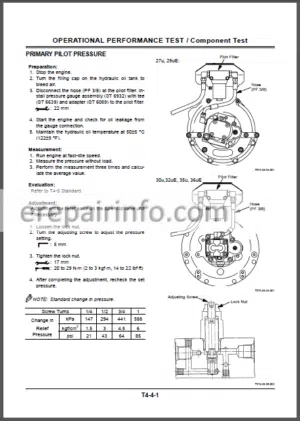
–COMPONENT TEST
Pilot Pressure
Main Relief Valve Pressure Setting
Overload Relief Valve Pressure Setting
Swing Motor Relief Valve Pressure Setting
–STANDARD
Performance Standard Table
–DIAGNOSING PROCEDURE
Introduction
Diagnosing Procedure
How to Read the Troubleshooting Flow Charts
Check Battery Voltage
EX Operation Manual for Auto Boom-Stop System
Fault Code List
Operation Record List
Monitoring Item List
System Operation Status
Troubleshooting Screen
Flowchart
–ENGINE CONTROL SYSTEM
Engine
Starter Does Not Rotate
–MONITOR SYSTEM
Monitor Panel
Fuse Fails
Malfunction of Coolant Temperature Gauge
Malfunction of Fuel Gauge
Malfunction of Alternator Indicator
Malfunction of Engine Oil Pressure Indicator
Malfunction of Overheat Indicator
Malfunction of Fuel Level Indicator
Malfunction of Air Filter Restriction Indicator
Malfunction of Buzzer
Malfunction of Hour Meter
Malfunction of Fast Travel Indicator
Electrical Test Precautions
Continuity Check
Voltage Check
–AUTO BOOM-STOP FUNCTION – HEIGHT RESTRICTION FUNCTION
Auto Boom-Stop Function Check
Pilot Control Shut-Off
Lever Circuit Check
Angle Sensor System Check
Height Restriction Function Check
–MACHINE OPERATION SYSTEM
Actuator System Troubleshooting
Front Attachment System Troubleshooting
Swing System Troubleshooting
Travel System Troubleshooting - -EXЗЗMU HYDRAULIC CIRCUIT
- -EX58MU HYDRAULIC CIRCUIT
What you get
You will receive PDF file with high-quality manual on your email immediately after the payment.


Reviews
There are no reviews yet.