Factory Service Repair Manual For Hitachi EX400-3 Excavators. Tons of illustrations, instructions, diagrams for step by step remove and install, assembly and disassembly, service, inspection, repair, troubleshooting, tune-ups.
Format: PDF
Language: English
Pages: 914
Bookmarks: Yes
Searchable: Yes
Wiring Diagrams: Yes
Hydraulic Diagrams: Yes
Model
Hitachi EX400-3
Contents
Workshop Manual
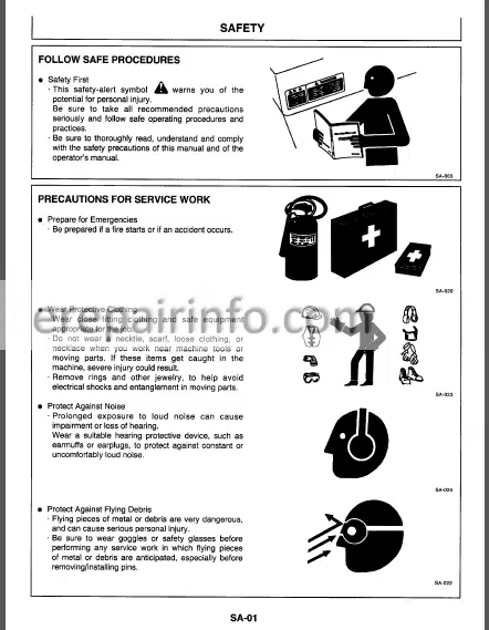
- SAFETY
- -GENERAL INFORMATION
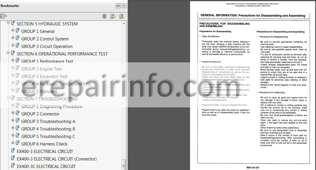
–PRECAUTIONS FOR DISASSEMBLING AND ASSEMBLING
Precautions for Disassembling and Assembling
–TIGHTENING TORQUE
Tightening Torque Specification
Torque Chart - -UPPERSTRUCTURE
–CAB
Remove and Install Cab
Dimensions of the Cab Glass
–COUNTERWEIGHT
Remove and Install Counterweight
–MAIN FRAME
Remove and Install Main Frame
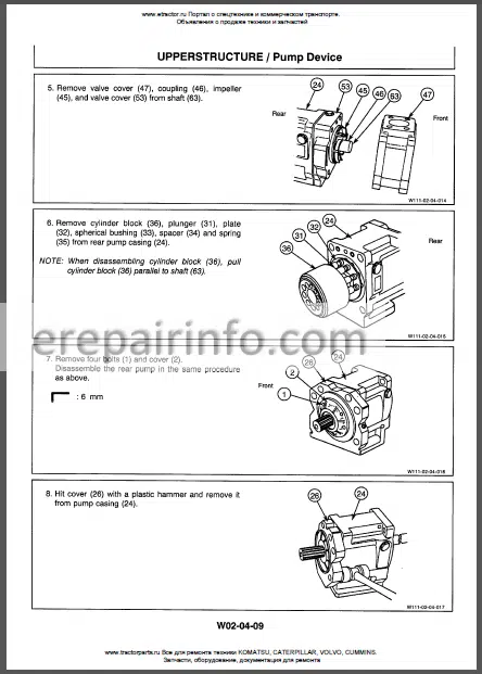
–PUMP DEVICE
Remove and Install
Pump Device
Disassemble Pump Transmission
Assemble Pump Transmission
Disassemble Main Pump
Assemble Main Pump
Maintenance Standard
–CONTROL VALVE
Remove and Install
Control Valve
Disassemble Control Valve
Assemble Control Valve
–SWING DEVICE
Remove and Install Swing Device
Disassemble Swing Reduction Gears
Assemble SwingReduction Gears
Disassemble Swing Motor
Assemble Swing Motor
Maintenance Standard
–PILOT VALVE
Remove and Install Left Pilot Valve
Remove and Install Right Pilot Valve
Disassemble Right and Left Pilot Valve
Assemble Right and Left Pilot Valve
Remove and Install Travel Pilot Valve
Disassemble Travel Pilot Valve Assemble Travel Pilot Valve
–PILOT SHUT-OFF VALVE
Remove and Install
Pilot Shut-off Valve
Disassemble Pilot Shut-off Valve
Assemble Pitot Shut-off Valve
–SHOCKLESS VALVE
Remove and Install Shockless Vatve (for Digging/Swing)
Disassemble and Assemble Shockless Valve (for Digging/Swing)
Remove and Install Shockless Vatve (for Traveling)
Disassemble and Assemble Shockless Valve (for Traveling)
–ACCUMULATOR
Remove and Install Accumulator
–Solenoid Valve
Remove and Install Solenoid Valve Unit
Disassemble and Assemble Solenoid Valve Unit
–SHUTTLE VALVE
Remove and Install Shuttle Valve
Disassemble and Assemble Shuttle Valve
–SWING DAMPENER VALVE
Remove and Install Swing Dampener Valve
Disassamble Swing Dampener Valve
Assemble Swing Dampener Valve
Disassemble Valve
Assemble Valve - -UNDERCARRIAGE
–SWING BEARING
Remove and Install
Swing Bearing
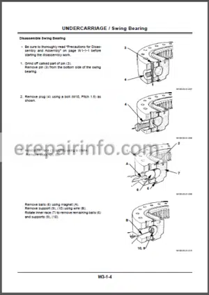
Disassemble Swing Bearing
Assemble Swing Bearing
–TRAVEL DEVICE
Remove and Install Travel Device
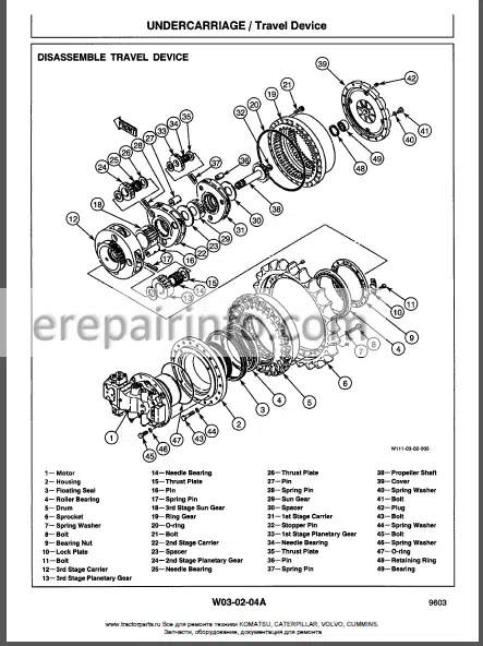
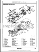
Disassemble Travel Device
Assemble Travel Device
Disassemble Travel Motor
Assemble Travel Motor
Disassemble Brake Valve
Assemble Brake Valve
Maintenance Standard
–CENTER JOINT
Remove and Install Center Joint Disassemble Center Joint
Assemble Center Joint
Maintenance Standard
–TRACK ADJUSTER
Remove and Install
Track Adjuster
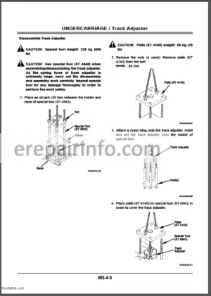
Disassemble Track Adjuster
Assemble Track Adjuster
–FRONT IDLER
Remove and Install Front Idler
Disassemble Front Idler
Assemble Front Idler
Maintenance Standard
–UPPER AND LOWER ROLLER
Remove and Install Upper Roller
Remove and Install Lower Roller
Disassemble Upper Roller
Assemble Upper Roller
Disassemble Lower Roller
Assemble Lower Roller
Maintenance Standard
–TRACK LINK
Remove and Install Track Link
Maintenance Standard - -FRONT ATTCHMENT
–FRONT ATTACHMENT
Remove and Install Front Attachment
Maintenance Standard
–CYLINDER
Removeand Install Cylinder
Disassembe Cylinder
Assemble Cylinder
Maintenance Standard - -SPECIAL TOOLS
–SPECIAL TOOL LIST
Special Tool List
–GENERAL INFORMATION
General Information
Notes on the Format of Engine Section
Main Data & Specifications
Design Features and General Outline
Tightening Torque Specifications Angular Nut & Bolt Tightening Method
Major Parts Fixing Nuts & Botts Identifications
–MAINTENANCE
Lubricating System
Fuel System
Cooling System
Valve Clearance Adjustment
Injection Timing
Compression Pressure Measurement
Turbocharger Inspection
Engine Repair Kit
Recommended Lubricants
Engine Oil Viscosity Chart
–ENGINE ASSEMBLY I (DISASSEMBLY)
Engine Assembly General Description
Disassembly 1 st Step
2nd Step
3rd Step
Cylinder Head Disassembly Step Piston And Connecting Rod Disassembly Step
Rocker Arm And Shaft Disassembly Step
Camshaft And Gear Disassembly Step
Crankshaft Disassembly Step
–ENGINE ASSEMBLY II (INSPECTION & REPAIR)
Cylinder Head
Valve Guide
Valve And Valve Seal Insert
Valve Spring
Tappet
Push Rod
Rocker Arm Shaft And Rocker Arm
Idler Gear And Idler Gear Shaft Camshaft
Cylinder Body And Liner
Piston And Piston Ring
Piston Pin
Connecting Rod
Crank Shaft And Bearing
Flywheel & Ring Gear
Timing Gear Case Cover
–ENGINE ASSEMBLY III (REASSEMBLY)
Piston And Connecting Rod Reassembly Step
Cylinder Head Reassembly Step Rocker Arm And Rocker Arm Shaft Reassembly Step
Reassembly 1st Step
Reassembly 2nd Step
Reassembly 3rd Step
Reassembly 4th Step
Engine Tuning Operation
–LUBRICATING SYSTEM
General Description
Oil Pump
Main Oil Filter
Oil Cooler
–COOLING SYSTEM
General Description
Water Pump
Thermostat
–FUEL SYSTEM
General Description
Fuel Filter
Injection Nozzle
–TURBO CHARGER
General Description
Identification
Rotor Shaft Play Inspection
–AIR COMPRESSOR (IF EQUIPPED)
General Description
Disassembly Step
Inspection & Repair
Reassembly Step
–ENGINE ELECTRICAL
Starter Motor
Alternator
Intake Heater
–TROUBLESHOOTING
Hard Starting
Unstable Low Idling
Insufficient Power
–SPECIAL TOOL
Special Tod
Technical Manual
- SAFETY
- -SPECIFICATIONS
–GENERAL INFORMATION
Foreword
Specifications
Working Range -Transporting Dimansions
Shoe Types & Applications
–FUELS AND LUBRICANTS
Service Refill Capacities
Fuel
Grease
Engine Oil
Gear Oil
Hydraulic System
Cooling System
–INTERCHANGEABILITY
Interchangeability
Installation of Attachments
–MACHINE NUMBERS
Machine Numbers
–COMPONENT SPECIFICATIONS
Engine
Engine Accessories
Hydraulic Devices
Filters
Electrical Equipment - -UPPERSTRUCTURE
–OUTLINE
Outline
–TANKS
Construction and Function
–PUMP DEVICE
Outline
Pump Transmission
Main Pump
Pump Regulator
Main Pump Control System
Pilot Pump
–SWING DEVICE
Outline
Swing Motor
Brake Valve
Swing Parking Brake
Swing Dampener Valve
Swing Reduction Gear
–CONTROL VALVE
Outline
Construction and Function
Oil Flow
Primary Circuit
Neutral Passages
Return Oil Passages
Parallel Oil Passages
Flow Combining Passages
Main Relief Valve
Pump Control Valve
Overload Relief Valve
Make-up Valve
Holding Valve
Arm Regenerative Valve
Automatic Air Bleeding Circuit
–PILOT VALVE
Outline
Construction
Function
Operation
–OTHERS
Pilot Shut-off Valve
Shockless Valve
Accumulator
Solenoid Valve
Swing Dampener Solenoid Valve Solenoid Valve Assembly
Pump Displacement Solenoid Valve - -UNDERCARRIAGE
–OUTLINE
Outline
–SWING BEARING
Construction and Function
–CENTER JOINT
Outline
–TRAVEL DEVICE
Outline
Travel Device Function
Travel Motor
Parking Brake
Travel Brake Valve
–TRACK ADJUSTER
Construction and Function - -ELECTRICAL SYSTEM
–COMPONENT LOCATION
Component Location
Relays
Monitor and Switch Panel
–CONTROL SYSTEM
Outline
Relationship Between Control Functions
and Input / Output signals
Outline of Engine Control System
Engine Control Motor Circuit
Setting of Engine Mode Speed
Engine Stop System
Functions of Main Electrical Equipment (Excluding Monitor System)
–MONITOR
Outline
Monitor Panel
Monitor Function
Monitor Check Procedure
–CIRCUIT OPERATION
Characteristics of the Electrical System
Power Circuit
Preheat Circuit
Engine Start Circuit
Charging Circuit
Surge Voltage Prevention Circuit
Accessory Circuit
EC Motor Engine Stop Circuit
Engine Stop Motor Circuit
Auto-Idle
–INSPECTION AND MAINTENANCE
Precautions for Inspection and Maintenance
Fuse Continuity Test
Taking apart Connectors
Inspection and Replacement of Fusible Links
Install and Adjustment of the A-Sensor
Positioning the EC Sensor
Installation of the EC Motor - -HYDRAULIC SYSTEM
–GENERAL
General
Hydraulic Circuit
Main Circuit
Pilot Circuit
–CONTROL SYSTEM
Pump Control
Travel Speed Control
–CIRCUIT OPERATION
Single Operation
Combined Operation - -OPERATIONAL PERFORMANCE TEST
–PERFORMANCE TEST
Concept of Performance Test
Conditions Performance Test
–ENGINE TEST
Engine Speed
Engine Compression Pressure
Valve Clearance Adjustment
Nozzle Check
Injection Timing Adjustment
–EXCAVATOR TEST
Travel Speed
Track Revolution Speed
Mistrack Check
Travel Parking Function Check
Swing Speed
Swing Function Drift Check
Swing Motor Leakage
Swing Bearing Play
Maximum Swingable Slant Angle
Hydraulic Cylinder Cycle Time
Dig Function Drift Check
Control Lever Operating Force
Control Lever Stroke
Combined Boom Raise I
Swing Function Check
–HYDRAULIC COMPONENT TEST
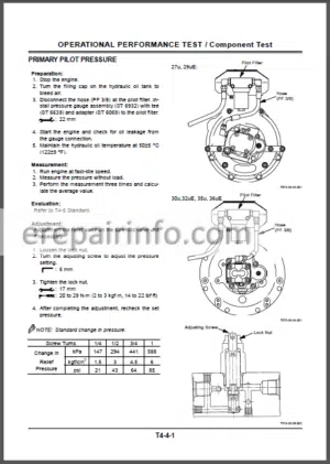
Pilot Primary Pressure
Pitot Secondary Pressure
Swing Preference Circuit Control Pressure (MA Pressure)
Main Relief Pressure Changeover Pressure (SA Pressure)
Travel speed Selecting Control Pressure (SB Pressure)
Swing Parking Brake Releasing Pressure (SC Pressure)
Main Relief Pressure (Non Power Boost)
Overload Relief Pressure (Power Boost)
Travel / Swing Relief Pressure
Travel Motor Drainage
Swing Motor Drainage
–STANDARD
Operational Performance
Standard - -TROUBLESHOOTING
–DIAGNOSING PROCEDURE
Introduction
Diagnosing Procedure
DrEX Start-Up Procedure
Self-diagnosing Function
Clearing the Self-Diagnosing Function
Retrial A
Retrial B
DrEX Monitor Function
Check Battery Voltage
Check Fuses
Check Fusible Link
–CONNECTOR
Connector Location
Type of Connector
–Troubleshooting A List of EC-Related Fault Codes
List of PVC-Related Fault Codes T07-03-02 Fault Codes 01,020304 and 06
Fault Code 05
Fault Codes 09 and 10
Fault Code 13
Fault Codes 17,18,19,21 and 22
Fault Code 20
Fault Code 23 and 24
Fault Codes 25,26,33 and 34
Fault Codes 27,28,35 and 36
Fault Codes 29,30,37 and 38 Fault Codes 14 and 15
–TROUBLESHOOTING B
Outline
Effects of Electronic Component Malfunctions Operations
Machine Malfunctions and Possible Causes
Engine Troubleshooting
Actuator Troubleshootings
Front Attachment Troubleshootings
Swing Troubleshooting
Travel Troubleshooting
Other Troubleshooting
–TROUBLESHOOING C
Monitor Panel Switch and Sensor Location
Malfunction of Coolant Temperature Gauge
Malfunction of Fuel Gauge
Malfunction of Level Check Switch
Malfunction of Engine Oil Level Indicator
Malfunction of Coolant Level Indicator
Malfunction of Hydraulic Oil Level Indicator
Malfunction of Alternator Indicator
Malfunction of Engine Oil Pressure Indicator
Malfunction of Overheat Indicator
Malfunction of Fuel Level Indicator
Malfunction of Air Filter Restriction Indicator
Malfunction of Buzzer
Malfunction of Hour Meter
–HARNESS CHECK
Electical Test Precautions
Continuity Check
Voltage Check
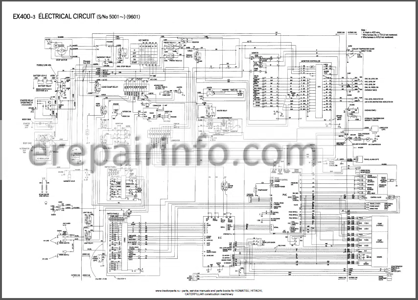
5 Volt Circuit - -EX400-3 ELECTRICAL CIRCUIT
- -EX400-3 ELECTRICAL CIRCUIT (CONNECTOR)
- -EX400-3C ELECTRICAL CIRCUIT
- -EX400-3C ELECTRICAL CIRCUIT (CONNECTOR)
What you get
You will receive PDF file with high-quality manual on your email immediately after the payment.

Reviews
There are no reviews yet.