


Factory Service Repair Manuals Set For Hitachi EX750-5, EX800H-5 Excavators. Tons of illustrations, instructions, diagrams for step by step remove and install, assembly and disassembly, service, inspection, repair, troubleshooting, tune-ups.
Format: PDF
Language: English
Bookmarks: Yes
Searchable: Yes
Wiring Diagrams: Yes
Hydraulic Diagrams: Yes
Model
Hitachi EX750-45, EX800H-5
Contents
1.Circuit shematics
2.Parts Catalog(Basic)
3.Parts Catalog(Equipment Components)
4.Technical Manual(OperationalPrinciple)
5.Technical Manual(Troubleshooting)
6.Workshop Manual
1.Technical Manual(OperationalPrinciple)
INTRODUCTION
-GENERAL
–SPECIFICATION
Specifications
Working Ranges/Transporting Dimensions
–COMPONENT SPECIFICATIONS
Engine
Engine Accessories
Hydraulic Components
Filters
Electrical Components
–COMPONENT LAYOUT
Main Components
Electrical System (1)
Electrical System (2)
Electrical System (3)
Control Valve
Other Components
-SYSTEM
–CONTROL SYSTEM
Outline
Engine Control
Pump Control
Valve Control
Other Control
–HYDRAULIC SYSTEM
Outline
Main Circuit
Pilot Circuit
–ELECTRICAL SYSTEM
Outline
Power Circuit
Bulb Check Circuit
Engine Start Circuit
Charging Circuit
Accessory Circuit
Surge Voltage Prevention Circuit
Engine Stop Circuit
-COMPONENT OPERATION
–PUMP DEVICE
Outline
Main Pump
Regulator
Pilot Pump
N Sensor (Engine Speed Sensor)
P Sensor (Pump Delivery Pressure Sensor)
A Sensor (Pump Displacement Angle Sensor)
–SWING DEVICE
Outline
Swing Motor
Valve Unit
Swing Parking Brake
Swing Reduction Gear
–CONTROL VALVE
Outline
Hydraulic Circuit
Flow Combiner Valve
Center Bypass Valve
Pump Control Valve
Main Relief Valve
Overload Relief Valve
Make-Up Valve
Holding Valve
Arm Regenerative Valve
–PILOT VALVE
Outline
Operation
–TRAVEL DEVICE
Outline
Travel Reduction Gear
Travel Motor
Travel Brake Valve
Travel Motor Displacement
Angle Shift
Parking Brake
–OTHERS (UPPERSTRUCTURE)
Pilot Shut-Off Valve
Shockless Valve
Solenoid Valve
Accumulator
–OTHERS (UNDERCARRIAGE)
Swing Bearing
Center Joint
Track Adjuster
2.Technical Manual(Troubleshooting)
INTRODUCTION
SAFETY
-OPERATIONAL PERFORMANCE TEST
–INTRODUCTION
Operational Performance Tests
Preparation for Performance Test
–ENGINE TEST
Engine Speed
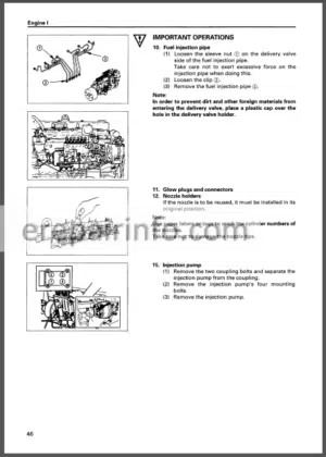
Injector and Valve Clearance
Adjustment
–EXCAVATOR TEST
Travel Speed
Track Revolution Speed
Mistrack Check
Travel Parking Function Check
Swing Speed
Swing Function Drift Check
Swing Motor Leakage
Maximum Swingable Slant Angle
Swing Bearing Play
Hydraulic Cylinder Cycle Time
Dig Function Drift Check
Control Lever Operating Force
Control Lever Stroke
Boom Raise I Swing Combined Operation Check
–COMPONENT TEST
Primary Pilot Pressure
Secondary Pilot pressure
Swing Preference Circuit Shift Control Pressure (MA Pressure)
Main Relief Pressure Shift Control
Pressure (SA Pressure)
Travel Mode Shift Control Pressure (SB Pressure)
Main Relief Pressure
Overload Relief Valve Set Pressure
Main Pump Flow Test
Swing Motor Drainage
Travel Motor Drainage
–STANDARD
Operational Performance Standard Table
-TROUBLESHOOTING
–DIAGNOSING PROCEDURE
Introduction
Diagnosing Procedure
Dr EX
Dr EX Start Up Procedure
Clearing the Self-Diagnosing Function
Retrial “A”
Retrial “B”
Fault code List
Monitoring Function
–COMPONENT LAYOUT
Main Components
Electrical System Component (1)
Electrical System Component (2)
Electrical System Component (3)
Control Valve
Others
–TROUBLESHOOTING A
Troubleshooting A Procedure
Fault Code List
Fault Codes 01, 02, 03, 04, 06 (EC Failure)
Fault Code 05 (Communication Failure between PVC and EC)
Fault Code 09, 10 (EC Sensor Failure)
Fault Code 11, 12 (Engine Control Dial Failure)
Fault Code 13 (N Sensor Failure)
Fault Code 14, 15 (Overheat Switch L Failure, Hydraulic Oil Temperature Sensor Failure)
Fault Codes 17, 18, 19, 21,22 (PVC Failure)
Fault Code 20 (Communication Failure between EC and PVC)
Fault Code 23, 24 (Pump Control Failure)
Fault Code 25, 26, 33, 34 (DP Sensor Failure)
Fault Code 27, 28, 35, 36 (P Sensor Failure)
Fault Code 29, 30, 37, 38 (A Sensor Failure)
Sensor Operating Range List
–TROUBLESHOOTING B
Troubleshooting B Procedure
Correlation between Part Failure and Abnormalities that Machine may Show
Correlation between Troubles and
Part Failures
Engine System Troubleshooting
Total Actuator System Troubleshooting
Front Attachment System Troubleshooting
Swing System Troubleshooting
Travel System Troubleshooting
Troubleshooting for Other Functions
Engine Speed Adjustment
EC Sensor Installation and Voltage Adjustment
–TROUBLESHOOTING C
Troubleshooting C Procedure
Malfunction of Coolant Temperature Gauge
Malfunction of Fuel Gauge
Malfunction of Indicator Bulb Check System
Malfunction of Level Check Switch
Malfunction of Engine Oil Level Indicator
Malfunction of Coolant Level Indicator
Malfunction of Hydraulic Oil Level Indicator
Malfunction of Alternator Indicator
Malfunction of Engine Oil Pressure Indicator
Malfunction of Overheat Indicator
Malfunction of Fuel Level Indicator
Malfunction of Air Filter Restriction Indicator
Malfunction of Hour Meter
Malfunction of Buzzer
Malfunction of Work Light Indicator
Malfunction of Quick Idle Indicator
–ELECTRICAL SYSTEM INSPECTION
Precautions for Inspection and Maintenance
Instructions for Disconnecting Connectors
Fuse Continuity Test
Fusible Link Inspection and Replacement
Battery Voltage Check
How to Troubleshoot Alternator Malfunctions
Continuity Check
Voltage and Current Check
Relay Replacing Procedure
–HARNESS CHECK
Circuit Check
3.Workshop Manual
INTRODUCTION
SAFETY
-GENERAL IMFORMATION
–PRECAUTIONS FOR DISASSEMBLING AND ASSEMBLING
Precautions for Disassembling and Assembling
Maintenance Standard Terminology
–TIGHTENING
Tightening Torque Specification
Torque Chart
Piping Joint
-UPPERSTRUCTURE
–CAB
Remove and Install Cab
Dimensions of the Cab Glass
–COUNTERWEIGHT
Remove and Install Counterweight
–PUMP DEVICE
Remove and InstallPump Device
Disassemble Pump Transmission
Assemble Pump Transmission
Remove and Install Main Pump
Disassemble Main Pump
Assemble Main Pump
Maintenance Standard
Disassemble Regulator
Assemble Regulator
Disassemble and Assemble Pilot Pump
–CONTROL VALVE
Remove and Install Control Valve
Disassemble Control Valve 1
Assemble Control Valve 1
Disassemble Control Valve 2
Assemble Control Valve 2
Disassemble Control Valve 3
Assemble Control Valve 3
Disassemble Control Valve 4
Assemble Control Valve 4
Disassemble Control Valve 5
Assemble Control Valve 5
–SWING DEVICE
Remove and Install Swing Device
Disassemble Swing Reduction Gears
Assemble Swing Reduction Gears
Disassemble Swing Motor
Assemble Swing Motor
Disassemble and Assemble Swing Parking Brake Release Valve
Maintenance Standard
–PILOT VALVE
Remove and Install Right Pilot Valve
Remove and Install Left Pilot Valve
Remove and Install Travel Pilot Valve
Disassemble Right and Left Pilot Valve
Assemble Right and Left Pilot Valve
Disassemble Travel Pilot Valve
Assemble Travel Pilot Valve
–PILOT SHUT-OFF VALVE
Remove and Install Pilot Shut-off Valve
Disassemble Pilot Shut-off Valve
Assemble Pilot Shut-off Valve
–SHOCKLESS VALVE
Remove and Install Front Attachment Shockless Valve
Disassemble and Assemble Shockless Valve (Front Attachment)
Remove and Install Travel Shockless Valve
Disassemble and Assemble Travel Shockless Valve
–SOLENOID VALVE
Remove and Install Two-Spool Solenoid Valve
Disassemble and Assemble Two-Spool Solenoid Valve
-UNDERCARRIAGE
–SWING BEARING
Remove and Install
Swing Bearing
Disassemble Swing Bearing
Assemble Swing Bearing
–TRAVEL DEVICE
Remove and Install
Travel Device
Disassemble Travel Device
Assemble Travel Device
Disassemble Travel Motor
Assemble Travel Motor
Disassemble Brake Valve
Assemble Brake Valve
Maintenance Standard
–CENTER JOINT
Remove and Install Center Joint
Disassemble Center Joint
Assemble Center Joint
Maintenance Standard
–TRACK ADJUSTER
Remove and Install Track Adjuster
Disassemble Track Adjuster
Assemble Track Adjuster
–FRONT IDLER
Remove and Install Front Idler
Disassemble Front Idler
Assemble Front Idler
Maintenance Standard
–UPPER AND LOWER ROLLER
Remove and Install Upper Roller
Remove and Install Lower Roller
Disassemble Lower Roller
Assemble Lower Roller
Disassemble Lower Roller
Assemble Lower Roller
Maintenance Standard
–TRACK
Remove and Install Track
Maintenance Standard
-FRONT ATTACHMENT
–FRONT ATTACHMENT
Remove and Install Front Attachment Cylinder and Preparation
Maintenance Standards
Air Bleeding Procedure
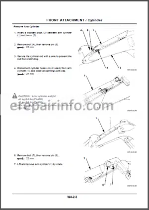
–CYLINDER
Disassemble Cylinder
Assemble Cylinder
Maintenance Standard
What you get
You will receive PDF file with high-quality manual on your email immediately after the payment.


Reviews
There are no reviews yet.