


Factory Service Repair Manuals For Hitachi Zaxis 180W Excavators. Tons of illustrations, instructions, diagrams for step by step remove and install, assembly and disassembly, service, inspection, repair, troubleshooting, tune-ups.
Format: PDF
Language: English
Pages: 720 + 413 + 369 + 13
Bookmarks: No
Searchable: Yes
Number: KM-CCBE
Wiring Diagrams: Yes
Hydraulic Diagrams: Yes
Model
Hitachi Zaxis 180W
Contents
1.Principle
2.Wiring Diagrams
3.Troubleshooting
4.Workshop Manual
Workshop Manual
- INTRODUCTION
SAFETY - -GENERAL INFORMATION
–PRECAUTIONS FOR DISASSEMBLING AND ASSEMBLING
Precautions for Disassembling and Assembling
Maintenance Standard Terminology
–TIGHTENING TORQUE
Tightening Torque Specification
Torque Chart
Piping Joint
Periodic Replacement of Parts
–PAINTING
Painting
–BLEEDING AIR FROM HYDRAULIC OIL TANK
Bleeding Air from Hydraulic Oil tank - -UPPERSTRUCTURE
–CAB
Remove and Install Cab
Dimensions of the Cab Glass
–COUNTERWEIGHT
Remove and Install Counterweight
–MAIN FRAME
Remove and Install Main Frame
–PUMP DEVICE
Remove and Install Pump Device
Disassemble Pump Device
Assemble Pump Device
Disassemble Regulator
Assemble Regulator
Disassemble Solenoid Valve
Assemble Solenoid Valve
Disassemble and Assemble
Pilot Pump
Maintenance Standard
–CONTROL VALVE
Remove and Install Control Valve
Disassemble 4-Spool Control Valve
Disassemble 5-Spool Control Valve
Separate and Combine 4-Spool and 5-Spool Sections
Assemble 4-Spool Control Valve
Assemble 5-Spool Control Valve
Remove and Install Auxiliary Control Valve
Disassemble Auxiliary Control Valve
Assemble Auxiliary Control Valve
–SWING DEVICE
Remove and Install Swing Device
Disassemble Swing Device
Assemble Swing Device
Disassemble Swing Motor
Assemble Swing Motor
Maintenance Standard
–PILOT VALVE
Remove and Install Pilot Valve
Disassemble Front/Swing Pilot Valve
Assemble Front/Swing Pilot Valve
Disassemble Travel,
Positioning/Auxiliary Blade/Stabilizer Pilot Valve
Assemble Travel, Positioning/Auxiliary Blade/Stabilizer Pilot Valve
–PILOT SHUT-OFF VALVE
Remove and Install
Pilot Shut-Off Valve
Disassemble Pilot Shut-Off Valve
Assemble Pilot Shut-Off Valve
–SIGNAL CONTROL VALVE
Remove and Install Signal
Control Valve
–TRAVEL SHOCKLESS VALVE
Remove and Install
Travel Shockless Valve
Construction of
Travel Shockless Valve
–SOLENOID VALVE
Remove and Install 4-Unit Solenoid Valve Unit
Disassemble Proportional Solenoid Valve
Assemble Proportional Solenoid Valve
Remove and Install Solenoid Valve (for Pump Control)
Construction of Solenoid Valve (for Pump Control)
Remove and Install 2-Unit Solenoid Valve (for Blade/Stabilizer)
Construction of 2-Unit Solenoid Valve (for Blade/Stabilizer)
–PILOT RELIEF VALVE
Remove and Install Pilot Relief Valve
Construction of Pilot Relief Valve
–STEERING VALVE
Remove and Install Steering Valve
Disassemble Steering Valve
Assemble Steering Valve
Disassemble and Assemble Check Valve Unit
–BRAKE VALVE
Remove and Install Brake Valve
Disassemble Brake Valve
Assemble Brake Valve
–ACCUMULATOR CHARGING VALVE
Remove and Install Accumulator Charging Valve
Construction of Accumulator Charging Valve
–TRANSMISSION CONTROL VALVE
Remove and Install Transmission Control Valve
Construction of Transmission Control Valve - -UNDERCARRIAGE
–Swing Bearing
Remove and Install Swing Bearing
Disassemble Swing Bearing
Assemble Swing Bearing
–Travel Motor
Remove and Install Travel Motor
Disassemble Travel Motor
Assemble Travel Motor
Disassemble Brake Valve
Assemble Brake Valve
–Center Joint
Remove and Install Center Joint
Disassemble Center Joint
Assemble Center Joint
Maintenance Standard
–Transmission
Remove and Install Transmission
Disassemble Transmission
Disassemble Final Drive and Differential
Assemble Final Drive and Differential
Assemble Transmission
Adjusting Gear Clearance
–AXLE
Remove and Install Axle
Disassemble Front Axle
Assemble Front Axle
Disassemble Front Differential
Assemble Front Differential
Disassemble Rear Axle
Assemble Rear Axle
Disassemble Rear Differential
Assemble Rear Differential
Disassemble Steering Cylinder
Assemble Steering Cylinder
–AXLE LOCK CYLINDER
Remove and Install Axle Lock Cylinder
Disassemble and Assemble Axle Lock Cylinder
–OPERATE-CHECK VALVE
Remove and Install Operate-Check Valve (for Axle Lock Cylinder)
Construction of Operate-Check Valve (for Axle Lock Cylinder)
–PROPELLER SHAFT
Remove and Install Propeller Shaft - -FRONT ATTACHMENT
–FRONT ATTACHMENT
Hydraulic Circuit Pressure Release Procedure
Remove and Install Monoblock Boom
Front Attachment
Remove and Install 2-Piece Boom Front Attachment
Maintenance Standard
Standard Dimensions for Arm and Bucket Connection
Standard Dimensions for Arm and Boom Connection
–CYLINDER
Remove and Install Cylinder (Monoblock Boom, 2-Piece Boom)….
Disassemble Cylinder (Boom (Monoblock/2-Piece), Positioning and Bucket)
Assemble Cylinder (Boom (Monoblock/2-Piece),Positioning and Bucket
Disassemble Cylinder (Arm)
Assemble Cylinder (Arm
Disassemble Cylinder (Stabilizer, Blade)
Assemble Cylinder (Stabilizer, Blade)
Maintenance Standard
–HOSE-RUPTURE SAFETY VALVE
Remove and Install Hose-Rupture Safety Valve
Construction of Hose-Rupture Safety Valve
–OPERATE-CHECK VALVE
Remove and Install Operate-Check Valve (for Blade/Stabilizer)
Construction of Operate-Check Valve (for Blade/Stabilizer) - -ENGINE AND ACCESSORY
–GENERAL INFORMATION
General Repair Instructions
Notes on the Format of This Manual
Main Data and Specifications
Performance Curve
External View
Tightening Torque Specifications
Angular Nut and Bolt Tightening Method
Major Parts Fixing Nuts and Bolts
Identifications
–MAINTENANCE
Lubricating System
Fuel System
Cooling System
Valve Clearance Adjustment
Injection Timing
Compression Pressure Measurement
Turbocharger Inspection
Engine Repair Kit
Recommended Lubricants
Engine Oil Viscosity Chart
–ENGINE ASSEMBLY 1 (DISASSEMBLY)
External Parts Disassembly Steps
Major Components
Rocker Arm and Rocker Arm Shaft
Disassembly Steps
Cylinder Head Disassembly Steps
Piston and Connecting Rod Disassembly Steps
–ENGINE ASSEMBLY 2 (INSPECTION AND REPAIR)
Cylinder Head
Valve Guide
Valve Spring
Tappet
Push Rod
Rocker Arm Shaft and Rocker Arm
Idler Gear and Idler Gear Shaft
Camshaft
Cylinder Body and Liner
Piston and Piston Ring
Piston Pin
Connecting Rod
Crankshaft
Flywheel
Timing Gear Case Cover
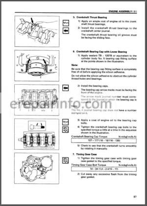
–ENGINE ASSEMBLY 3 (REASSEMBLY)
Piston and Connecting Rod Reassembly Steps
Cylinder Head Reassembly Steps
Rocker Arm and Rocker Arm Shaft
Reassembly Steps
Major Component Reassembly Steps 1
Major Component Reassembly Steps 2
External Parts Reassembly Steps (Left-Hand Side)
External Parts Reassembly Steps (Right-Hand Side)
Engine Tuning Operation
–LUBRICATING SYSTEM
General Description
Oil Pump
Oil Cooler
–COOLING SYSTEM
General Description
Thermostat
–FUEL SYSTEM
General Description
Injection Nozzle
Injection Pump Calibration Data
–TURBOCHARGER
General Description
Turbocharger Identification
Troubleshooting
Inspection and Repair
–ENGINE ELECTRICALS
Starter Identification
Starter Main Data and Specifications
Starter Sectional View
Performance
Disassembly
Inspection and Repair
Reassembly
Adjustment
Performance Test
Alternator Identification
Main Data and Specifications
Alternator Sectional View
Charging Circuit
Structure
Disassembly
Inspections
Reassembly
Bench Test
Current Output Test
Fault Finding
Specifications
–TROUBLESHOOTING
Hard Starting
1)Starter Inoperative
2)Starter Operates but
Engine does not Turn Over
3)Engine Turns Over but does not Start
Fuel is Being Delivered to the Injection Pump
4)Engine Turns Over but does not Start
Unstable Low Idling
Insufficient Power
Excessive Fuel Consumption
Excessive Oil Consumption
Overheating
Whity Exhaust Smoke
Dark Exhaust Smoke
Oil Pressure does not Rise
Abnormal Engine Noise
–SPECIAL TOOL LIST
Special Tool List
–REPAIR STANDARDS
Repair Standards
–CONVERSION TABLE
Length
Area
Volume
Mass
Pressure
Torque
Temperature
Troubleshooting
- INTRODUCTION
SAFETY - -OPERATIONAL PERFORMANCE TEST
–INTRODUCTION
Operational Performance Tests
Preparation for Performance Tests
–STANDARD
Operational Performance Standard Table
Main Pump P-Q Diagram
Injection Pump
DrZX Monitor Indicating Values
Sensor Activating Range
–ENGINE TEST
Engine Speed
Engine Compression Pressure
Valve Clearance Adjustment
Nozzle Check
Injection Timing
Lubricant Consumption
–EXCAVATOR TEST
Travel Speed
Service Brake Function Check
Parking Brake Function Check
Swing Speed
Swing Function Drift Check
Swing Motor Leakage
Maximum Swingable Slant Angle
Swing Bearing Play
Hydraulic Cylinder Cycle Time
Dig Function Drift Check
Control Lever Operating Force
Control Lever Stroke
Combined Boom Raise/Swing Function Check
–COMPONENT TEST
Primary Pilot Pressure
Secondary Pilot Pressure
Solenoid Valve Set Pressure
Main Pump Delivery Pressure
Main Relief Valve Set Pressure
Relief Pressure (When relieving Swing)
Relief Pressure (When relieving Travel)
Overload Relief Valve Set Pressure
Main Pump Flow Rate Measurement
Regulator Adjustment
Swing Motor Drainage
Travel Motor Drainage
Steering Valve Relief Valve Set Pressure
Brake Pressure (Front and Rear)
Brake Accumulate Pressure
Brake Warning Set Pressure (Decrease)
Brake Warning Set Pressure (Increase)
–ADJUSTMENT
Engine Speed Adjustment and Engine Learning
Governor Lever and Fuel Cut Lever
Position - -TROUBLESHOOTING
–GENERAL
Introduction
Diagnosing Procedure
Built-In Diagnosing System Operation
Built-In Diagnosing Function
Display List
Dr ZX Operation
Dr ZX Fault Code List (MC)
Dr ZX Monitoring Item List
Dr ZX Special Function
Dr ZX Service Mode
Adjustment Data List
–COMPONENT LAYOUT
Main Component Layout
Electrical Component Layout (Overview)
Electrical System (Relays)
Electrical System(Monitors and Switches)
Ele ctrical System (Column Box)
Pump Device
Swing Device
Signal Control Valve
Control Valve
Auxiliary control Valve
4-Unit Solenoid Valve Unit
3-Unit Solenoid Valve Unit
Travel Shockless Valve / Accumulator Chrging Valve
Transmission Control Valve
Travel Device
Filter
Components in Control Valve
Signal Control Valve Port Location
–TROUBLESHOOTING A
Troubleshooting A Procedure
Fault Code List
Fault Code 01, 02, 03
Fault Code 04
Fault Code 06
Fault Code 07
Fault Code 10, 11
Fault Code 12, 13
Fault Code 14, 15, 16, 18, 23, 24
Fault Code 19
Fault Code 20
Fault Code 22
–TROUBLESHOOTING B
Troubleshooting B Procedure
Relationship between Machine Trouble Symptoms and Related Parts
Correlation between Trouble Symptoms and Part Failures
Engine System Troubleshooting
All Actuator System Troubleshooting
Front Attachment System Troubleshooting
Swing System Troubleshooting
Travel System Troubleshooting
Brake System Troubleshooting
Steering System Troubleshooting
Other System Troubleshooting
Exchange Inspection
Bleeding Air from Transmission
Bleeding Air from Brake (Axle)
Emergency Boom Lowering Procedure (without Hose-Rupture Safety Valve)
Emergency Boom Lowering Procedure (with Hose-Rupture Safety Valve)
–TROUBLESHOOTING C
Troubleshooting C Procedure
Malfunction of Coolant Temperature Gauge
Malfunction of Fuel Gauge
Malfunction of Indicator Light Check System
Malfunction of Preheat Indicator
Malfunction of Overheat Indicator
Malfunction of Air Filter Restriction Indicator
Malfunction of Fuel Level Indicator
Malfunction of Alternator Indicator
Malfunction of Engine Oil Pressure Indicator
Malfunction of Hydraulic Oil Filter Indicator (Optional)
–ELECTRICAL SYSTEM INSPECTION
Precautions for Inspection and Maintenance
Instructions for Disconnecting Connectors
Fuse Inspection
Fusible Link Inspection
Battery Voltage Check
How to Troubleshoot Alternator Malfunctions
Continuity Check
Voltage and Current Measurement
Check by False Signal
Test Hamess
–ICX
Outline
ICX Fault Code List
Fault Code 1 to 6
Fault Code 7 to 10
Some Parts of Data in Daily Report, Frequency Distribution, Cumulative Operation Hours are not Recorded
Principle
- INTRODUCTION
- -GENERAL
–SPECIFICATIONS
Specifications
Working Ranges
–COMPONENT LAYOUT
Main Component Layout
Electrical Component Layout (Overview)
Electrical System (Relays)
Electrical System (Monitors and Switches)
Electrical System (Column Box)
Pump Device
Swing Device
Signal Control Valve
Control Valve
Auxiliary control Valve
4-Unit Solenoid Valve Unit
Pump Control Solenoid Valve
Travel Shockless Valve / Accumulator Charging Valve
Transmission Control Valve
Travel Device
Filter
–COMPONENT SPECIFICATIONS
Engine
Engine Accessories
Hydraulic Component
Electrical component - -SYSTEM
–CONTROL SYSTEM
Outline
Engine Control
Pump Control
Valve Control
Other Controls
Electric and Hydraulic
Composite Circuit Control
–HYDRAULIC SYSTEM
Outline
Pilot Circuit
Service Brake Circuit
Steering Circuit
Main Circuit
–ELECTRICAL SYSTEM
Outline
Main Circuit
Electric Power Circuit
Indicator Light Check Circuit
Accessory Circuit
Preheat Circuit
Starting Circuit
Charging Circuit
Parking Brake Circuit
Serge Voltage Prevention Circuit
Engine Stop Circuit - -COMPONENT OPERATION
–PUMP DEVICE
Outline
Main Pump
Regulator
Solenoid Valve
Pilot Pump, Steering Pump
N Sensor (Engine Speed Sensor)
Pump Delivery Pressure Sensor
Pump Control Pressure Sensor
–SWING DEVICE
Outline
Swing Reduction Gear
Swing Motor
Swing Parking Brake
Valve Unit
–CONTROL VALVE
Outline
Hydraulic Circuit
Flow Combiner Valve
Main Relief Valve
Overload Relief Valve
Regenerative Valve
Anti-Drift Valve
Flow Rate Control Valve
Bypass Shut-Out Valve
Auxiliary Flow Combiner Valve
–PILOT VALVE
Outline
Operation
–TRAVEL DEVICE
Outline
Transmission
Front and Rear Propeller Shaft
Front Axle
Steering Cylinder
Differential Gear
Reduction Gear
Rear Axle
Travel Motor
Rotor Section
Regulator
Brake Valve
–SIGNAL CONTROL VALVE
Outline
Pilot Port
Shuttle Valve
Shockless Valve
Pump 1 and Pump 2 Flow Rate
Control Valves
Bucket Flow Rate Control Valve Control Spool, Flow Combiner Valve Control Spool, Swing Parking Brake Release Spool, Arm Flow Rate Control Valve Control Spool
–STEERING VALVE
Outline
Construction
Operation
Relief Valve
Overload Relief Valve
Make-Up Valve
–BRAKE VALVE
Outline
Operation
–TRANSMISSION CONTROL VALVE
Outline
Operation
–OTHERS (UPPERSTRUCTURE)
Pilot Shut-Off Valve
Solenoid Valve Unit
Travel Shockless Valve
Pilot Relief Valve
Accumulator
Accumulator Charging Valve
Hose-Rupture Safety Valve
EC Motor
–OTHERS (UNDERCARRIAGE)
Swing Bearing
Center Joint
Slip Ring
Cylinder
What you get
You will receive PDF file with high-quality manual on your email immediately after the payment.


Reviews
There are no reviews yet.