


Factory Service Repair Manual For Hitachi Zaxis 27U-2 30U-2 35U-2 Excavators. Tons of illustrations, instructions, diagrams for step by step remove and install, assembly and disassembly, service, inspection, repair, troubleshooting, tune-ups.
Format: PDF
Language: English
Pages: 551
Bookmarks: Yes
Searchable: Yes
Number: KM-1MJ-E
Wiring Diagrams: Yes
Hydraulic Diagrams: Yes
Model
Hitachi 27U-2, 30U-2, 35U-2
Contents
1.Diagrams
2.Technical Manual
3.Workshop Manual
Workshop Manual
- -GENERAL INFORMATION
–PRECAUTIONS FOR DISASSEMBLING AND ASSEMBLING
Precautions for Disassembling and Assembling
–TIGHTENING
Tightening Torque Specification
Torque Chart
Piping Joint
Periodic Replacement of Parts
–PAINTING
Painting
–BLEEDING AIR
Bleed Air from Hydraulic Oil Tank
–FLOOR-TILTING DEVICE
Floor-Tilting Device Operation
Procedure
Procedure for Floor Tilting up
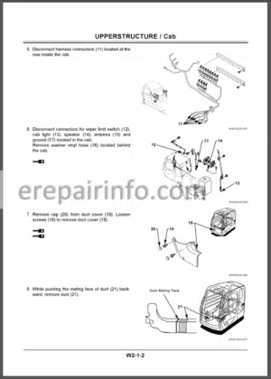
Procedure for Floor Tilting down - -UPPERSTRUCTURE
–CANOPY
Remove And Install Canopy
–COUNTERWEIGHT
Remove And Install
Counterweight - -PUMP DEVICE
Remove And Install
Pump Device
Disassemble Pump Device
Assemble Pump Device
Maintenance Standards
–CONTROL VALVE
Remove And Install Control Valve
Disassemble And Assemble
Control Valve
Disassemble And Assemble Body
Disassemble Boom Anti-Drift Valve
Assemble Boom Anti-Drift Valve
Disassemble And Assemble Spool
Disassemble And Assemble Arm
Regenerative Valve, Check Valve And Orifice
–SWING DEVICE
Remove and Install
Swing Device
Disassemble Swing Device
Assemble Swing Device
Disassemble Swing Motor
Assemble Swing Motor
Maintenance Standards
–PILOT VALVE
Remove and Install Front Pilot Valve
Remove and Install Travel Pilot Valve
Remove and Install Blade Pilot Valve
Remove and Install Boom Swing
Pilot Valve
Disassemble Right and Left
Pilot Valves
Assemble Right and Left Pilot Valves
Disassemble Travel Pilot Valve
Assemble Travel Pilot Valve
Disassemble Pilot Valves for
Boom Swing, Blade and Auxiliary
Assemble Pilot Valves for
Boom Swing, Blade and Auxiliary
Group 7 Solenoid Valve
Remove and Install Solenoid Valve
Disassemble 2-Unit Solenoid Valve
Assemble 2-Unit Solenoid Valve
1-Unit Solenoid Valve
Structure of 1-Unit Solenoid Valve - -UNDERCARRIAGE
–SWING BEARING
Remove and Install Swing Bearing
–TRAVEL DEVICE
Remove and Install Travel Device
Disassemble Travel Device
Assemble Travel Device
Disassemble Travel Motor
Assemble Travel Motor
Disassemble and Assemble
Brake Valve
Maintenance Standards
–CENTER JOINT
Remove and Install Center Joint (ZAXIS27U-2)
Disassemble Center Joint (ZAXIS27U-2)
Assemble Center Joint(ZAXIS27U-2)
Remove and Install Center Joint (ZAXIS30U-2, 35U-2)
Disassemble Center Joint (ZAXIS30U-2, 35U-2)
Assemble Center Joint (ZAXIS30U-2, 35U-2)
–TRACK ADJUSTER
Remove and Install Track Adjuster
Disassemble Track Adjuster
Assemble Track Adjuster
–FRONT IDLER
Remove and Install Front Idler
Disassemble and Assemble Front Idler
Maintenance Standards
–UPPER AND LOWER ROLLER
Remove and Install Upper Roller
Remove and Install Lower Roller
Disassemble and Assemble
Lower Roller
Maintenance Standards
–TRACK
Remove and Install Tracks
Maintenance Standards - -FRONT ATTACHMENT
–FRONT ATTACHMENT
Remove and Install Front Attachment
Maintenance Standards
Standard Dimensions for Arm and Bucket Connection
–CYLINDER
Remove and Install Cylinders
Disassemble Boom and Arm Cylinders
Assemble Boom and Arm Cylinders
Disassemble Bucket and Boom Swing Cylinders
Assemble Bucket and Boom Swing Cylinders
Disassemble Blade Cylinder
Assemble Blade Cylinder
Maintenance Standards - -ENGINE AND ACCESSORY
–GENERAL
Engine Nomenclature
Specifications
Fuel Oil, Lubricating Oil and Cooling Water
Engine External Views
Structural Description
Exhaust Gas Emission Regulation
–INSPECTION AND ADJUSTMENT
Periodic Maintenance Schedule
Periodic Inspection and Maintenance Procedure
Adjusting the No-load Maximum or Minimum Speed
Sensor Inspection
Water Leak Check in
Cooling Water System
Radiator Cap Inspection
Thermostat Inspection
Adjusting Operation
Long Storage
–TROUBLESHOOTING
Preparation before Troubleshooting
Quick Reference Table for Troubleshooting
Troubleshooting by Measuring
Compression Pressure
–DISASSEMBLY, INSPECTION AND REASSEMBLY OF ENGINES
Complete Disassembly and Reassembly
Cylinder Head: Disassembly Inspection and Reassembly
Gear Train and Camshaft
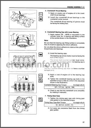
Cylinder Block
–LUBRICATION SYSTEM
Lubrication System Diagram
Trochoid Pump Components
Disassembly (Reverse the Procedure below for Assembly)
Servicing Points
Parts Inspection and Measurement
–COOLING SYSTEM
Cooling Water System
Cooling Water Pump Components
Disassembly (Reverse the Procedure below for Assembly)
Servicing Points
–FUEL INJECTION PUMP / GOVERNOR
Introduction
Fuel Injection Pump
–TURBOCHARGER: DISASSEMBLY, INSPECTION AND REASSEMBLY
Structure and Functions
Service Standards and Tightening Torque
Periodic Inspection Procedure
Disassembly Procedure
Washing and Inspection Procedure
Reassembly Procedure
Handling after Disassembly and Reassembly
Troubleshooting
–STARTING MOTOR
For4TNV94L/98
For4TNV106(T)
–ALTERNATOR
The 40A Alternator for 3TNV84 and Other Models
–ELECTRIC WIRING
Electric Wiring Diagram
Precaution on Electric Wiring
–SERVICE STANDARDS
Engine Tuning
Engine Body
Lubricating Oil System (Trochoid Pump)
–TIGHTENING TORQUE FOR BOLTS AND NUTS
Tightening Torques for Main Bolts and Nuts
Tightening Torques for Standard
Bolts and Nuts
Technical Manual
- INTRODUCTION
SAFETY - -GENERAL
–SPECIFICATION
Specifications
Working Ranges and Machine Dimensions for Transportation
–COMPONENT LAYOUT
Main Component Layout
Electrical Component Layout (Overview)
Electrical System (Controllers and Relays)
Electrical System (Monitor and Switches)
Engine
Swing Device
Control Valve (ZAXIS27U-2)
Control Valve (ZAXIS30U-2, 35U-2)
Travel Device
2-Unit Solenoid Valve
Torque Control Solenoid Valve (Only Machine with Air Conditioner Attached)/ Flow Selector Solenoid Valve (Optional)
–COMPONENT SPECIFICATIONS
Engine
Engine Accessories
Hydraulic Component
Filter
Electrical Component - -SYSTEM
–CONTROL SYSTEM
Outline
Engine Control
Pump Control
Front Attachment Control
Other Control
–HYDRAULIC SYSTEM
Outline
Pilot Circuit
Main Circuit
–ELECTRICAL SYSTEM
Outline
Power Circuit (key Switch : OFF)
Power Circuit (Key Switch : ON)
Preheating Circuit (Key Switch : HEAT)
Starting Circuit (Key Switch : START)
Charging Circuit (Key Switch : ON)
Engine Stop Circuit (Key Switch : OFF) - -COMPONENT OPERATION
–PUMP DEVICE
Outline
Main Pump (P1, P2)
Main Pump (P3), Pilot Pump (P4)
Horse Power Control Operation
–SWING DEVICE
Outline
Swing Motor
Parking Brake
Valve Unit
Swing Reduction Gear
–CONTROL VALVE
Outline
Hydraulic Circuit
Arm Regenerative Valve
Boom Anti-Drift Valve
Flow Combiner Valve
Flow Rate Combining Selector Valve
Main Relief Valve
Overload Relief Valve
Make-Up Valve
–PILOT VALVE
Outline
Operation
Shockless Function (Only for Travel Pilot Valve)
Shuttle Valve (Optional)
–TRAVEL DEVICE
Outline
Travel Motor
Parking Brake
Travel Brake Valve
Travel Reduction Gear
–OTHERS (UPPERSTRUCTURE)
2-Unit Solenoid Valve
Pilot Relief Valve
Torque Control Solenoid Valve (Only Machine with Attached Air Conditioner)/ Flow Selector Solenoid Valve (Optional)
Group 7 Others (Undercarriage)
Swing Bearing
Center Joint
Track Adjuster - -OPERATIONAL PERFORMANCE TEST
–INTRODUCTION
Operational Performance Test
Preparation for Performance Tests
–STANDARD
Operational Performance Standard
Main Pump P-Q Diagram (ZAXIS27U-2)
Main Pump P-Q Diagram (ZAXIS30U-2, 35U-2)
–ENGINE TEST
Engine Speed
Engine Compression Pressure
Valve Clearance
Nozzle Check
Injection Timing
–EXCAVATOR TEST
Travel Speed
Track Revolution Speed
Mistrack Check
Travel Motor Leakage
Swing Speed
Swing Function Drift Check
Swing Motor Leakage
Maximum Swingable Slant Angle
Swing Bearing Play
Hydraulic Cylinder Cycle Time
Dig Function Drift
Control Lever Operating Force
Control Lever Stroke
Combined Boom Raise/Swing
Function Check
–COMPONENT TEST
Primary Pilot Pressure
Secondary Pilot Pressure
Main Relief Valve Set Pressure
Overload Relief Valve Set Pressure
Pump Driving Torque
Swing Motor Drainage’
Travel Motor Drainage’
–ADJUSTMENT
Fuel Lever Adjustment (ZAXIS27U-2 Only) - -TROBLESHOOTING
–DIAGNOSING PROCEDURE
Introduction
Diagnosing Procedure
–TROUBLESHOOTING A
Troubleshooting A Procedure
Error Indication List
Wire Breakage and Short Circuit of Engine Control Dial (System Failure Indicator: Flickering Every 1 Sec)
Motor Sensor Breakage and Short Circuit (System Failure Indicator: Flickering Every 05 Sec)
Abnormal Motor (System Failure Indicator: Lit)
–TROUBLESHOOTING B
Troubleshooting B Procedure
Engine System Troubleshooting
Actuator Operating System Troubleshooting
Front Attachment System Troubleshooting
Swing System Troubleshooting
Travel System Troubleshooting
Blade System Troubleshooting
Boom Swing System Troubleshooting
How to Lower Boom when Engine Stops
How to Prevent Hom Blowing at Key Switch Position of OFF
–TROUBLESHOOTING C
Troubleshooting C Procedure
Malfunction of Coolant Temperature Gauge
Malfunction of Fuel Gauge
Malfunction of Preheat Indicator
Malfunction of Alternator Indicator
Malfunction of Engine Oil Pressure Indicator
Malfunction of Overheat Indicator
Malfunction of Fuel Level Indicator
Malfunction of Monitor Buzzer
Malfunction of Liquid Crystal Display (LCD)
Malfunction of Hour Meter
Malfunction of Auto-Idle Indicator
–ELECTRICAL SYSTEM INSPECTION
Precautions for Inspection and Maintenance
Fuse Continuity Test
Battery Voltage Check
Voltage Check
Continuity Check
What you get
You will receive PDF file with high-quality manual on your email immediately after the payment.


Reviews
There are no reviews yet.