


Factory Service Repair Manuals set For Hitachi ZX 140W-3 Excavators. Tons of illustrations, instructions, diagrams for step by step remove and install, assembly and disassembly, service, inspection, repair, troubleshooting, tune-ups.
Format: PDF
Language: English
Bookmarks: Yes
Searchable: Yes
Wiring Diagrams: Yes
Hydraulic Diagrams: Yes
Model
Hitachi ZX 140W-3
Contents
1.Technical Manual(Operational Principle)
2.Electrical Schematics 1
3.Technical Manual(Troubleshooting)
4.Electrical Schematics 2
5.Workshop Manual
INTRODUCTION
SAFETY
-GENERAL
–PRECAUTIONS FOR DISASSEMBLING AND ASSEMBLING
Precautions for Disassembling and Assembling
Maintenance Standard Terminology
–TIGHTENING
Tightening Torque Specification
Torque Chart
Piping Joint
Periodic Replacement of Parts
–PAINTING
Painting
–BLEEDING AIR FROM HYDRAULIC OIL TANK
Bleeding Air from Hydraulic Oil tank
-UPPERSTRUCTURE
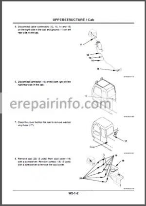
–CAB
Removal and Installation of Cab
Dimensions of Cab Glass
–COUNTERWEIGHT
Removal and Installation of Counterweight
–MAINFRAME
Removal and Installation of Main Frame
–PUMP DEVICE
Removal and Installation of Pump Device
Disassembly of Pump Device
Assembly of Pump Device
Disassembly of Regulator
Assembly of Regulator
Structure of Pilot Pump
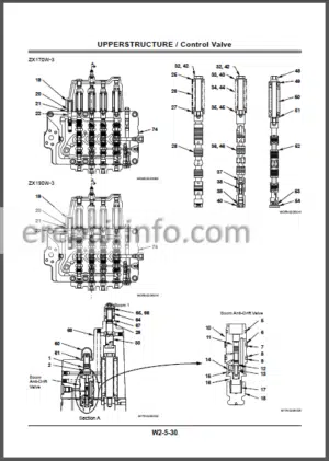
–CONTROL VALVE
Removal and Installation of Control Valve
Disassembly of Control Valve 4-Spool Side
Disassembly of Control Valve5-Spool Side
Assembly and Disassembly of 4-Spool Side and 5-Spool Side
Assembly of Control Valve 4-Spool Side
Assemble of Control Valve 5-Spool Side
Removal and Installation of Positioning Control Valve
Disassembly of Positioning Control Valve
Assembly of Positioning Control Valve
–SWING DEVICE
Removal and Installation of Swing Device
Disassembly of Swing Device
Assembly of Swing Device
Disassembly of Swing Motor
Assembly of Swing Motor
Disassembly of Valve Unit
Assembly of Valve Unit
Structure of Swing Dampener Valve
Maintenance Standard
–PILOT VALVE
Removal and Installation of Pilot Valve
Removal and Installation of
Travel Pilot Valve
Disassembly of Front/Swing Pilot Valves
Assembly of Front/Swing Pilot Valves
Disassembly of Travel and Auxiliary/Positioning Pilot Valves
Assembly of Travel and Auxiliary/Positioning Pilot Valves
–ELECTRIC LEVER
Removal and Installation of Electric Lever
Disassembly of Electric Lever
Assembly of Electric Lever
–SIGNAL CONTROL VALVE
Removal and Installation of Signal Control Valve
Structure of Signal Control Valve
–SHOCKLESS VALVE
Removal and Installation of Shockless Valve
Structure of Swing Shockless Valve
Structure of Travel Shockless Valve
–SOLENOID VALVE
Removal and Installation of 3-Spool Solenoid Valve Unit
Structure of 3-Spool Solenoid Valve Unit
Disassembly and Assembly of 3-Spool Solenoid Valve Unit
Removal and Installation of Solenoid Valve Unit (For Electric Lever Operation)
Structure of Solenoid Valve Unit (For Electric Lever Operation)
Removal and Installation of 1-Spool Solenoid Valve Unit
Structure of 1-Spool Solenoid Valve Unit
–PILOT SHUT-OFF SOLENOID VALVE
Removal and Installation of Pilot Shut-Off Solenoid Valve
Structure of Pilot Shut-Off Solenoid Valve
–STEERING VALVE
Removal and Installation of Steering Valve
–BRAKE VALVE
Removal and Installation of Brake Valve
Disassembly of Brake Valve
Assembly of Brake Valve
–ACCUMULATOR CHARGE VALVE
Removal and Installation of Accumulator Charge Valve
Structure of Accumulator Charge Valve
-UNDERCARRIAGE
–SWING BEARING
Removal and Installation of Swing Bearing
Disassembly of Swing Bearing
Assembly of Swing Bearing
–TRAVEL MOTOR
Removal and Installation of Travel Motor
Disassembly of Travel Motor
Assembly of Travel Motor
Disassembly of Brake Valve
Assembly of Brake Valve
–CENTER JOINT
Removal and Installation of Center Joint
Disassembly of Center Joint
Assembly of Center Joint
Maintenance Standard
–TRANSMISSION
Removal and Installation of Transmission
Disassembly of Transmission
Assembly of Transmission
–AXLE
Removal and Installation of Axle
Disassembly of Front Axle
Assembly of Front Axle
Disassembly of Rear Axle
Assembly of Rear Axle
Disassembly of Differential
Assembly of Differential
–AXLE LOCK CYLINDER
Removal and Installation of Axle Lock Cylinder
Disassembly and Assembly of Axle Lock Cylinder
–OPERATE CHECK VALVE
Removal and Installation of Operate Check Valve (for Axle Lock Cylinder)
Structure of Operate Check Valve (For Axle Lock Cylinder)
–SOLENOID VALVE
Removal and Installation of Outrigger/Blade Solenoid Valve Unit
Structure of Solenoid Valve Unit
–TRANSMISSION CHANGEOVER SOLENOID VALVE
Removal and Installation of Transmission Changeover Solenoid Valve
–PROPELLER SHAFT
Removal and Installation of Propeller Shaft
-FRONT ATTACHMENT
–FRONT ATTACHMENT
Hydraulic Circuit Pressure Release Procedure
Removal and Installation of Front Attachment (Monoblock Boom)
Removal and Installation of Front Attachment (2-Piece Boom)
Maintenance Standard
Standard Dimensions for Arm and Bucket Connection
Standard Dimensions for Arm and Boom Connection
–CYLINDER
Hydraulic Circuit Pressure
Release Procedure
Removal and Installation of Cylinder
Disassembly of Boom, Arm and Bucket Cylinders
Assembly of Boom Arm and Bucket Cylinders
Disassembly of Positioning Cylinder
Assembly of Positioning Cylinder
Disassembly of Outrigger and Blade Cylinders
Assembly of Outrigger and Blade Cylinder
Maintenance Standard
–HOSE RUPTURE VALVE
Hydraulic Circuit Pressure Release Procedure
Removal and Installation of Hose Rupture Valve for Arm Cylinder
Removal and Installation of Hose Rupture Valve for Positioning Cylinder
Removal and Installation of Hose Rupture Valve for Boom Cylinder
Structure of Hose Rupture Valve for Arm Cylinder
Structure of Hose Rupture Valves for Boom and Positioning Cylinders
–OPERATE CHECK VALVE
Remove and Install Operate Check Valve (for Blade and Outrigger)
Structure of Operate Check Valve
What you get
You will receive PDF file with high-quality manual on your email immediately after the payment.


Reviews
There are no reviews yet.