


Factory Technical Manual and Workshop Manual For Hitachi ZX17U-2 Excavators. Tons of illustrations, instructions, diagrams for step by step remove and install, assembly and disassembly, service, inspection, repair, troubleshooting, tune-ups.
Format: PDF
Language: English
Searchable: Yes
Number: W1MS-E-01
Wiring Diagrams: Yes
Hydraulic Diagrams: Yes
Model
Hitachi ZX17U-2
Contents
1. Technical Manual
INTRODUCTION
SAFETY
-GENERAL
–SPECIFICATION
Specifications
Working Ranges and Machine Dimensions for Transportation
–COMPONENT LAYOUT
Main Component Layout
Electrical Component Layout (Overview)
Electrical System (Relays)
Electrical System (Monitor and Switches)
Engine
Swing Device
Control Valve
Travel Device
2-Spool Solenoid Valve
–COMPONENT SPECIFICATIONS
Engine
Engine Accessories
Hydraulic Component
Filter
Electrical Component
-SYSTEM
–HYDRAULIC SYSTEM
Outline
Pilot Circuit
Main Circuit
–ELECTRICAL SYSTEM
Outline
Main Circuit
Electrical Power Circuit (key Switch: OFF)
Electrical Power Circuit (Key Switch: ON)
Preheating Circuit (Key Switch: HEAT)
Starting Circuit (Key Switch: START)
Charging Circuit (Key Switch: ON)
Engine Stop Circuit (Key Switch: OFF)
Monitor Circuit
Indicator Circuit
Work Light/ Internal Illumination Circuit
Gauge Circuit
Travel Alarm Circuit
-COMPONENT OPERATION
–PUMP DEVICE
Outline
Main Pump P1, P2
Main Pump P3, Pilot Pump P4
Horse Power Control Operation
–SWING DEVICE
Outline
Swing Motor
Parking Brake
Valve Unit
–CONTROL VALVE
Outline
Hydraulic Circuit
Arm Regenerative Valve
Flow Combiner Valve
Main Relief Valve
Overload Relief Valve
Make-Up Valve
–PILOT VALVE
Outline
Operation
Shockless Function (Only for Travel Pilot Valve)
–TRAVEL DEVICE
Outline
Travel Motor
Parking Brake
Travel Brake Valve
Travel Reduction Gear’
–OTHERS (UPPERSTRUCTURE)
2-Spool Solenoid Valve
Pilot Relief Valve
–OTHERS (UNDERCARRIAGE)
Swing Bearing
Center Joint
Track Adjuster
–OPERATIONAL PERFORMANCE TEST
–INTRODUCTION
Operational Performance Test
Preparation for Performance Tests
–STANDARD
Operational Performance Standard
Main Pump P-Q Diagram
–ENGINE TEST
Engine Speed
Engine Compression Pressure
Valve Clearance
Nozzle Check
Injection Timing
–EXCAVATOR TEST
Travel Speed
Track Revolution Speed
Mistrack Check
Travel Motor Leakage
Swing Speed
Swing Function Drift Check
Swing Motor Leakage
Maximum Swingable Slant Angle
Swing Bearing Play
Hydraulic Cylinder Cycle Time
Dig Function Drift
Control Lever Operating Force
Control Lever Stroke
Combined Boom Raise/Swing Function Check
–COMPONENT TEST
Primary Pilot Pressure
Secondary Pilot Pressure
Main Relief Valve Set Pressure
Overload Relief Valve Set Pressure
Pump Driving Torque
Swing Motor Drainage
Travel Motor Drainage
–ADJUSTMENT
Fuel Lever Adjustment
-TROUBLESHOOTING
–DIAGNOSING PROCEDURE
Introduction
Diagnosing Procedure
–TROUBLESHOOTING B
Troubleshooting B Procedure
Engine System Troubleshooting
Actuator System Troubleshooting
Front Attachment System Troubleshooting
Swing System Troubleshooting
Travel System Troubleshooting
Boom Swing System Troubleshooting
Blade System Troubleshooting
Side Frame Extend / Retract System Troubleshooting
How to Lower Boom In Case of Emergency and when Engine Stops
–TROUBLESHOOTING C
Troubleshooting C Procedure
Malfunction of Coolant Temperature Gauge
Malfunction of Fuel Gauge
Malfunction of Preheat Indicator
Malfunction of Alternator Indicator
Malfunction of Engine Oil Pressure Indicator
Malfunction of Overheat Indicator
Malfunction of Fuel Level Indicator
Malfunction of Monitor Buzzer
Malfunction of Hour Meter
–ELECTRICAL SYSTEM INSPECTION
Precautions for Inspection and Maintenance
Fuse Continuity Test
Battery Voltage Check
Voltage Check
Continuity Check
2.Workshop Manual
INTRODUCTION
SAFETY
-GENERAL
–PRECAUTIONS FOR DISASSEMBLING AND ASSEMBLING
Precautions for Disassembling and Assembling
–TIGHTENING
Tightening Torque
Tightening Bolts and Nuts
Piping Joint
Periodic Replacement Parts
–PAINTING
Painting
–BLEEDING AIR FROM HYDRAULIC OIL TANK
Bleeding Air from Hydraulic Oil Tank (Canopy Spec)
Bleeding Air from Hydraulic Oil Tank (Cab Spec)
-UPPERSTRUCTURE
–CANOPY AND CAB
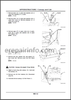
Removal and Installation of Canopy (2-Pillar)
Removal and Installation of Canopy (3-Pillar)
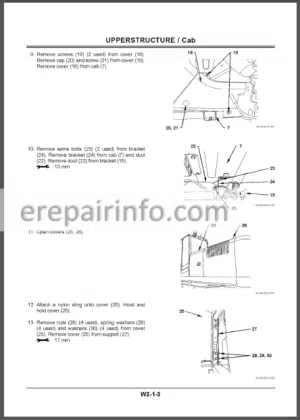
Removal and Installation of Cab
Dimensions of Cab Glass
–COUNTERWEIGHT
Removal and Installation of Counterweight (Canopy Spec Machine)
Removal and Installaton of Counterweight (Cab Spec Machine)
–MAIN FRAME
Removal and Installation of Main Frame
–PUMP DEVICE
Removal and Installation of Pump Device
Disassembly of Pump Device
Assembly of Pump Device
Maintenance Standard
–CONTROL VALVE
Removal and Installation of Control Valve
Disassembly and Assembly of Control Valve
Disassembly of Body
Assembly of Body
Disassembly of Spool
Assembly of Spool
Disassembly and Assembly of Check Valve
–SWING DEVICE
Removal and Installation of Swing Device
Disassembly of Swing Device
Assembly of Swing Device
–PILOT VALVE
Removal and Installation of Left Pilot Valve
Removal and Installation of Right Pilot Valve
Removal and Installation of Travel Pilot Valve
Removal and Installation of Blade Pilot Valve
Removal and Installation of Boom Swing Pilot Valve
Disassembly of Left and Right Pilot Valves
Assembly of Left and Right Pilot Valves
Disassembly of Travel Pilot Valve
Assembly of Travel Pilot Valve
Disassembly of Pilot Valves for Boom Swing, Blade, and Auxiliary
Assembly of Pilot Valves for Boom Swing, Blade, and Auxiliary
–SOLENOID VALVE
Removal and Installaiton of Solenoid Valve
Disassembly of 2-Spool Solenoid Valve
Assembly of 2-Spool Solenoid Valve
-UNDERCARRIAGE
–SWING BEARING
Removal and Installation of Swing Bearing
–TRAVEL DEVICE
Removal and Installation of Travel Device
Disassembly of Travel Device
Assembly of Travel Device
Disassembly of Travel Motor
Assembly of Travel Motor
Disassembly of Brake Valve
Assembly of Brake Valve
Maintenance Standard
–CENTER JOINT
Removal and Installation of Center Joint
Disassembly of Center Joint
Assembly of Center Joint
–TRACK ADJUSTER
Removal and Installation of Track Adjuster
Disassembly of Track Adjuster
Assembly of Track Adjuster
–FRONT IDLER
Removal and Installation of Front Idler
Disassembly of Front Idler
Assembly of Front Idler
Maintenance Standard
–UPPER AND LOWER ROLLER
Removal and Installation of Lower Roller
Structure of Lower Roller
Maintenance Standard
–TRACK
Removal and Installation of Track
Maintenance Standard
-FRONT ATTACHMENT
–FRONT ATTACHMENT
Hydraulic Circuit Pressure Release Procedure
Removal and Installation of Front Attachment
Maintenance Standard
Standard Dimensions for Arm and Bucket Connection
–CYLINDER
Hydraulic Circuit Pressure Release Procedure
Removal and Installation of Cylinder
Disassembly of Boom Cylinder
Disassembly of Arm, Bucket, Blade, Boom Swing, and Side Frame Extend/Retract Cylinders
Assembly of Boom Cylinder
Assembly of Arm, Bucket, Blade, Boom Swing, and Side Frame Extend/Retract Cylinders
Maintenance Standard
-ENGINE
–INTRODUCTION
–YANMAR WARRANTIES
Yanmar Limited Warranty
Emission System Warranty
Yanmar Co, Ltd Limited Emission Control System Warranty – USA Only
–SAFETY
Safety Statements
Safety Precautions
–GENERAL SERVICE INFORMATION
Component Identification
Location of Labels
EPA / ARB Emission Control
Regulations – USA Only
Emission Control Labels
The 97/68/EC Directive Certified Engines
Engine Family
Function of Major Engine Components
Function of Cooling System Components
Diesel Fuel
Engine Oil
Engine Coolant
Specifications
Principal Engine Specifications
Engine Service Information
Tightening Torques for Standard
Bolts and Nuts
Abbreviations and Symbols
Unit Conversions
–PERIODIC MAINTENANCE
Introduction
Precautions
Periodic Maintenance Schedule
Periodic Maintenance Procedures
–ENGINE
Before You Begin Servicing
Introduction
Cylinder Head Specifications
Camshaft and Timing Gear Train Specifications
Crankshaft and Pistons Specifications
Cylinder Block Specifications
Special Torque Chart
Special Service Tools
Measuring Instruments
Cylinder Head
Cylinder Block
–Fuel System
Before You Begin Servicing
Introduction
Fuel System Specifications
Special Service Tools
Measuring Instruments
Fuel System Diagram
Fuel System Components
Fuel Injection Lines
Fuel Injection Pump
Checking and Adjusting Fuel Injection Timing
Fuel Injectors
Disassembly and Inspection of Fuel Injectors
Adjusting Fuel Injector Pressure
Reassembly of Fuel Injectors
Installation of the Fuel Injectors
–Cooling System
Before You Begin Servicing
Introduction
Cooling System Diagram
Engine Coolant Pump Components
Engine Coolant System Check
Engine Coolant Pump
–Lubrication System
Before You Begin Servicing
Introduction
Oil Pump Service Information
Lubrication System Diagram
Checking Engine Oil Pressure
Trochoid Oil Pump
–STARTER MOTOR
Before You Begin Servicing
Introduction
Starter Motor Information
Starter Motor Specifications
Starter Motor Troubleshooting Starter Motor Components
Starter Motor
–ALTERNATOR
Before You Begin Servicing
Introduction
Standard and Optional Dynamo Information
Standard and Optional Alternator Information
Alternator Specifications
Dynamo Specifications
Alternator Troubleshooting
Alternator Components
Alternator Wiring Diagram
Alternator Standard Output
Alternator
Dynamo Component Location
Dynamo Wiring Diagram
Operation of Dynamo
Dynamo Standard Output
Testing of Dynamo
Dynamo
–ELECTRIC WIRING
Electric Wiring Precautions
Electric Wire Resistance
Battery Cable Resistance
Electrical Wire Sizes – Voltage Drop
Conversion of AWG to European Standards
–TROUBLESHOOTING
Special Service Tools
Troubleshooting By Measuring Compression Pressure
Quick Reference Table For Troubleshooting Troubleshooting Charts
Electric Wiring
What you get
You will receive PDF file with high-quality manual on your email immediately after the payment.


Reviews
There are no reviews yet.