


Factory Service Manual For JCB Telescopic Handler. Manual Contains Illustrations, Instructions, Diagrams For Step By Step Remove And Install, Assembly And Disassembly, Service, Inspection, Repair, Troubleshooting, Tune-Ups.
Format: PDF
Language: English
Pages: 701
Number: 9803/3600U
Searchable: Yes
Wiring Diagrams: Yes
Hydraulic Diagrams: Yes
Model
JCB Telescopic Handler
505-19
505-22
Serial No. from 561001 to 579365
508-40
Serial No. from 562601 to 579365
506-36
Serial No. from 563359 to 579999
510-40
Serial No. from 564542 to 579365
506B
Serial No. from 570000 to 579766
508-40
PlaceAce
Servo Options
505-19
505-22
Basic Servo Options
506-36
Servo Options
Contents
-GENERAL
Fluids, Lubricants, Capacities & Specifications
Service Schedules
Greasing
Oiling
Boom Safety Strut
-HYDRAULICS
Technical Data
General Description
Hydraulic Fluid Level & Filter
Draining Fluid & Cleaning Suction Strainers
Hydraulic Tank Removal & Replacement
Pump Operation
Pump Removal & Replacement
Machine Neutral Circuit
Boom Lift Operation
Boom Lower Operation
Hose Burst Operation
Boom Extend/Retract Operation
Sway Operation
Boom Extend Regenerative
Boom Extend High Pressure
Boom Retract
Stabilizer Check Valve Operation
Stabilizer Operation
M.R.V. Operation
A.R.V. Operation
Boom Extend Regenerative (506B)
Boom Extend High Pressure (506B)
Boom Retract (506B)
Hose Burst Operation I506B)
Boom Extend Regenerative Combined Valve (506B)
Boom Extend High Pressure Combined Valve (506B)
Boom Retract Combined Valve (506B)
Hose Burst Operation Combined Valve (506B)
Control Valve Block Removal & Replacement
Control Valve Block Dismantle & Assembly
Dual Function Controls Assembly
Pressure Testing
Lift Rams Removal & Replacement
Displacement Rams Removal & Replacement
Extension Cylinder Removal & Replacement
Tilt Cylinder Removal A Replacement
Sway Cylinder Removal & Replacement
Tow Hitch Cylinder Removal & Replacement
Inner Extension Cylinder Removal & Replacement
Outer Extension Cylinder Removal & Replacement
Stabilizer Cylinder Removal & Replacement
Boom Extension Circuit Bleeding Procedure
Extension Cylinder Make Up Valve
Diverter Valve Removal & Replacement
Diverter Valve Dismantle & Assembly
Hose Burst Protection Valve (506B)
Typical Cylinder Dismantle & Assembly
Tow Hitch Cylinder Dismantle & Assembly
Typical Cylinder with Uowel Head Dismantle & Assembly
Fan Motor Removal. Replacement & Adjustment
Fan Motor (Sundstrand) Dismantle & Assembly
Fan Motor (Ultra) Dismantle & Assembly
Schematic Hydraulic Circuit
-BODY AND FRAMEWORK
Boom Shimming
Inner Boom Removal & Replacement
Boom Removal & Replacement
Boom bxtend Chain Removal & Replacement 5Q6B
Boom Retract Chair Removal & Replacement 506B
Boom Chains Adjustment 506B
Boom Chains Inspection 506B
Cab Removal & Replacement
Front Windshield Removal & Replacement^
Rear Window Removal & Replacement
Side Window Removal & Replacement
Roar Window Hinged
Q – Fit Carriage Removal & Replacement
Fuel Tank Removal & Replacement
Air Conditioning Option
-PLACEACE CONTROL SYSTEM
Technical Data
Control System Description
Valve Block Operation
Pulsar Description & Operation
Valve Block Removal & Replacement
Pulsar Solenoid Removal & Replacement ~
Main Spool Removal & Replacement
Boom Angle Sensor Removal & Replacement
Boom Extension Sensor Removal & Replacement
Attitude Sensor Removal & Replacement
Motion Pac Control Unit Removal & Replacement
Driver Cards Removal & Replacement
Display Unit Removal & Replacement
Joystick Removal & Replacement ~
Lever Control (Stabilisers) Removal & Replacement
Control Valve Dismantle & Assembly
Valve Stack Dismantle & Assembly
Pressure Testing
Pull System Calibration
Vehicle Attitude & Tachometer Signal Calibration
Pulsar Solenoid Calibration
Driver Card Calibration/Adjustment
Functional Checks
Fault Finding
Schematic Hydraulic Circuit 508-40, 510-40
Schematic Electrical Circuit 508-40. 510-40
-SERVO CONTROL SYSTEM
Technical Data
Basic Servo Control System Description
Servo Control System Description
Valve Block-Qpstalian.
Valve Block Main Spool Operation
Joystick Control Lever Operation
Cab & Chassis Electrical Circuits Description
Valve Block Removal & Replacement
Control Valve Section Dismantle & Assembly
Control Valve Inlet & Outlet Dismantle & Assembly
Joystick Removal & Replacement
Lever Control Removal & Replacement
Pressure Testing
Bench Testing Joystick Control Levers
Bench Testing Sway/Stabilizer Control Levers
Fault Finding
Schematic Hydraulic Circuit
Schematic Electrical Circuit
-ENGINE
Technical Data
General Description
Engine Cover
Engine Oil Filter
Fuel Filter
Fuel Pump
Bleeding
Cooling System
Alternator Drive Belt
Pre-Cleaner
Air Filter
Radiator
Engine Removal & Replacement
Exhauster Removal & Replacement
Turbo Charger Engine Insulation
Naturally Aspirated Engine Insulation
-TRANSMISSION
Syncro Shuttle Technical Data
Syncro Shuttle General Description
Powershift Technical Data
Recovery Procedure
Checking & Changing Oil
Syncro Shutle General Description & Operation
Syncro Shuttle Operation
Syncromesh Description
Four Wheel Drive Clutch Operation (4 wheel drive)
Four Wheel Drive Clutch Operation (2 wheel drive)
Powershift General Description
Powershift Operation
Syncro Shuttle Fault Finding
Powershift Fault Finding
Transmission Removal & Replacement
Torque Converter Removal & Replacement
Syncro Shuttle Dismantling
Syncro Shuttle Assembly
Solenoid Valve Dismantling & Assembly
Reverser Unit Dismantling
Reverser Unit Assembly
Reverser Unit (Later Type) Dismantling
Reverser Unit (Later Type) Assembly
Mechanical 4 Wheel Drive Dismantling
Mechanical 4 Wheel Drive Assembly
Hydraulic 4 Wheel Drive Dismantling ~
Hydraulic 2/4 Wheel Drive IP 67 Machines
Pressure Testing 2/4WD Clutch
2/4WD Clutch Fault Finding
Torque Converter Stall Test
Piston Ring Seal Fitting Procedure
Powershift
-AXLES
Technical Data
Road Wheel Removal & Replacement
Water Ballast Tires
Front Axle breather Removal & Replacement
Axle Oil Level
Cutaway of Front Axle
Cutaway of Rear Axle
Front Axle (Fixed)
Front Axle (Sway)
Rear Axle
Hub (Dowel) & Driveshaft Dismantling
Front Hub (Splined) & Driveshaft Dismantling
Front Hub (Splined) & Driveshaft Assembly
Rear Hub (Splined), Brakes & Driveshaft Dismantling
Rear Hub (Splined), Brakes & Driveshaft Assembly
Brakes Dismantling
Brakes Assembly
Front Drive Head Dismantling
Front Drive Head Assembly
Renewing Axle Pinion Oil Seal
Rear Drive Head Dismantling
Rear Drive Head Assembly
Limited Slip Differential Dismantle & Assembly
-BRAKES
Technical data
Parking Brake Adjusting & Testing
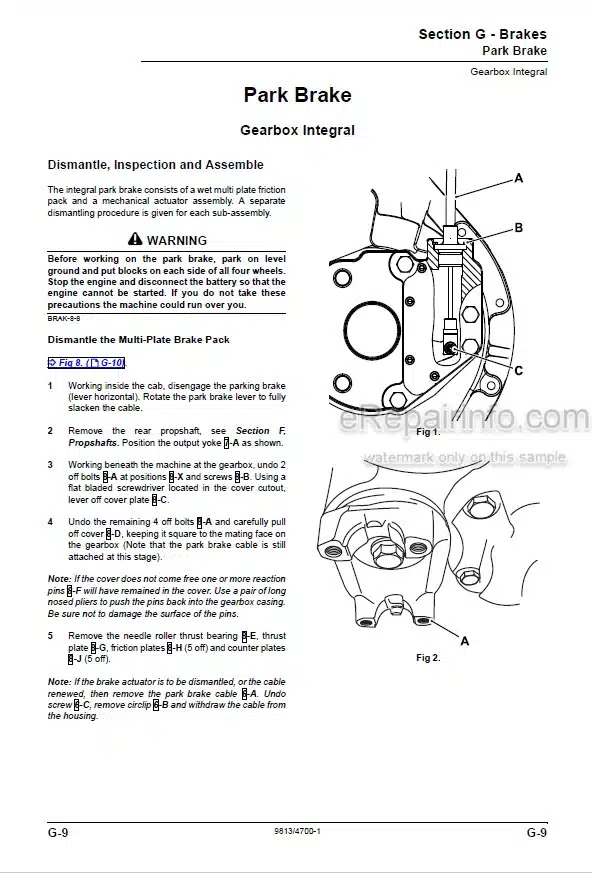
Parking Brake Dismantling & Assembly
Brake System Bleeding (Front Axle)
Brake System Bleeding (Rear Axle)
Single Master Cylinder Without Servo
Single Master Cylinder With Servo
Tandem Master Cylinder With Servo
-HYDRAULIC STEERING
Technical Data
General Description
Flow Regulating Valve Operation
Tandem Steering/Fan Pump Dismantling & Assembly
Steering/Fan Pump Removal & Replacement
Single Steering/Fan Pump Dismantling & Assembly
System Operation (Machines Without IP67 Electrics)
System Operation (Machines With IP67 Electrics)
Steering Description
Steering Shock Valve Description
Priority Valve Description
Steering Unit Removal & Replacement
Steering Unit Dismantling & Assembly
Steering Mode Valve Removal & Replacement
Steering Mode Valve Dismantling & Assembly
Steering Ram Removal & Replacement
Steering Ram Dismantling & Assembly
Bleeding
Pressure Testing
-ELECTRICS
Introduction
Technical Data
Fuses
Relay Location
Test Methods
Batteries Testing
Alternator
Starting Circuit Test
Starter Motor
Fault Finding
Harness Repair
Wiring Diagram
-SERVICE TOOLS
Numerical List
Section List
Sealing and Retaining Compounds
-BOOM FLOAT, RETURN TO DIG OPTION
Numerical List
Description
Schematic Hydraulic Circuit
Wiring Diagram
Relay Location
Fault Finding
Micro Switch Adjustment
Proximity Switch Adjustment
Hose Burst Solenoid
Removal & Replacement
Displacement Isolation Valve & Pressure Switch
What you get
You will receive PDF file with high-quality manual on your email immediately after the payment.


Reviews
There are no reviews yet.