


Factory Service And Maintenance Manual For JLG Boom Lift. Manual Contains Important Information And Instructions For Maintenance Description Of The Functions And Capabilities Of The System. Illustrations, Instructions, Diagrams For Step By Step Remove And Install, Assembly And Disassembly, Service, Inspection, Repair, Troubleshooting, Tune-Ups.
Format: PDF
Language: English
Pages: 582
Number: 3121160 (october 2017)
Bookmarks: Yes
Searchable: Yes
Wiring Diagrams: Yes
Hydraulic Diagrams: Yes
Model
JLG Boom Lift
740AJ
Prior to SN 0300185827
Contents
-INTRODUCTION – MAINTENANCE SAFETY PRECAUTIONS
General
Hydraulic System Safety
Maintenance
-SPECIFICATIONS
Operating Specifications
Component Data
Torque Requirements
Lubrication
Cylinder Specifications
Major Component Weights
Pressure Settings
Maintenance and Lubrication
Draining Oil Build Up From The Propane Regulator (Prior to SN 0300134626)
Propane Fuel Filter Replacement
Propane Fuel System Pressure Relief
-GENERAL
Machine Preparation, Inspection, and Maintenance
Service and Guidelines
Lubrication and Information
Cylinder Drift Test
Pins and Composite Bearing Repair Guidelines
Welding on JLG Equipment
-CHASSIS & TURNTABLE
Tires & Wheels
Emergency Towing
Wheel Drive Assembly (Prior to SN 0300138447)
Wheel Drive Assembly (SN 0300138447 through 0300185827)
Drive Hub (Prior to SN 0300185827)
Drive Brake – Mico (Prior to SN 0300138447)
Drive Brake (SN 0300138447 through 0300185827)
Drive Motor (Prior to SN 0300138447)
Drive Motor (SN 0300138447 through 0300185827)
Swing Bearing
Swing Hub Removal
Swing Hub Installation
Swing Hub (Prior to SN 0300074383)
Swing Hub (SN 0300074383 through 0300134352)
Swing Drive Brake (Prior to SN 0300134352)
Swing Motor (Prior to SN 0300134352)
Swing hub (SN 0300134353 through 0300185827)
Swing Motor (SN 0300134353 through 0300185827)
Rotary Coupling (Prior to SN 0300138447)
Rotary Coupling (SN 0300138447 through 0300185827)
Tilt Alarm Switch
Spark Arrester Cleaning Instructions
Deutz Engine
Ford Engine
GM Engine
Generator
Dual Fuel System
EFI Engine
Ford LPG System
Electric Governor Installation and Adjustments – Ford LRG425 Engine
Deutz EMR 2
GM Engine General Maintenance
GM Engine Dual Fuel System
GM Engine Fuel System Repair
GM Engine LPG Fuel System Diagnosis
Air Compressor
-BOOM & PLATFORM
Platform
Rotator and Slave Cylinder
Main Boom Powertrack
Powertrack Maintenance
Boom Cleanliness Guidelines
Main Boom Assembly
Upright
Tower Boom Assembly
Articulating Jib Boom
Limit Switches Adjustment
Platform
Wear Pads
Rotator – Helac (Prior to SN 0300130881)
Rotator Assembly (SN 0300130881 through 0300185827)
Drive Card Setup Procedures
Foot Switch Adjustment
Upright Monitoring System
UMS Troubleshooting and Fault Messages Non-ADE Machines
UMS Troubleshooting and Fault Messages-ADE Machines
Use and Care of Fall Arrest System
Platform Load Sensing System
-BASIC HYDRAULIC INFORMATION AND SCHEMATICS
Lubricating 0-Rings in the Hydraulic System
Valves – Theory Of Operation
Holding Valve Checks
Cylinders – Theory Of Operation
Cylinder Checking Procedure
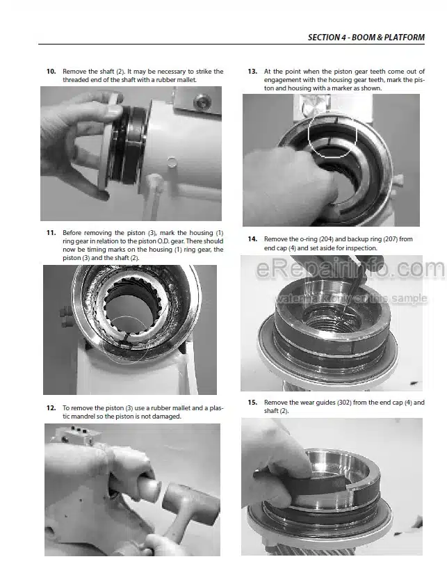
Cylinder Repair
Cylinder Removal and Installation
Hydraulic Pump W/Hayes Pump Drive Coupling Lubrication
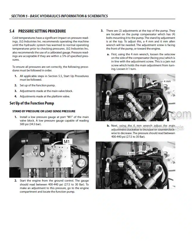
Pressure Setting Procedures
Hydraulic Oil Change-Out Procedure
Hydraulic Component Start-Up Procedures and Recommendations
Rexroth Variable Displacement Pump (Prior to SN 0300121643)
Sauer Piston Pump
Eaton Piston Pump
Hydraulic Schematics
-JLG CONTROL SYSTEM
JLG Control System Analyzer Kit Instructions
CANbus Communications
Machine Orientation When Doing Speed Tests
Machine Personality Settings
-BASIC ELECTRICAL INFORMATION & SCHEMATICS
General
Multimeter Basics
Applying Silicone Dielectric Compound to Electrical Connections
AMP Connector
Deutsch Connectors
Electrical Schematics
What you get
You will receive PDF file with high-quality manual on your email immediately after the payment.


Reviews
There are no reviews yet.