Factory Operation And Tests For John Deere Combine. Manual Contains Illustrations, Instructions, Diagrams For Systems Diagnosis, Theory Of Operation, Performance Testing, Tests And Adjustments, Operational Check, Unit Locations, Diagnostic Codes, Schematics And A Lot Of Other Useful Information For Service And Repair.
Format: PDF
Language: English
Pages: 304
Searchable: Yes
Wiring Diagrams: Yes
Hydraulic Diagrams: Yes
Model
John Deere Cameco Chopper Combine
CH2500
Contents
-SAFETY RECOMMENDATIONS
Safety and You
Operation Safety
Service Safety
Safety in Your Service Area
Safety when Cleaning or Storing
Safety Nevers
Recognize Safety Information
Understand Signal Words
Follow Safety Instructions
Protect Bystanders
Use Handles and Steps
Prevent Machine Runaway
Avoid Exhaust Fumes
Keep Riders off Machine
Handle Fuel Safely — Avoid Fires
Safely Service Accumulator
Safely Service Cooling System
Prepare For Emergencies
Wear Protective Clothing
Use Safety Lights and Devices
Use Cylinder Safety Stops
Practice Safe Maintenance
Avoid High Pressure Fluids
Use Caution on Hillsides
Stopping and Parking
Service Tires Safely
Transport Combine Safely
Avoid Electrical Power Lines
Keep Hands Away From Knives
Avoid Contact with Moving Parts
Dispose of Waste Properly
Fire Prevention
Safety Recommendations
Combine Safety
—GENERAL SPECIFICATIONS
250 HP Specifications
250 HP Description
250 HP Preliminary Service Intervals
250 HP Common Engine Wear Parts
325 HP Specifications
325 HP Description
325 HP Preliminary Service Intervals
325 HP Common Engine Wear Parts
Specifications
Description
Preliminary Service Intervals
Common Engine Wear Parts
Standard Efficiency Hydraulic
Transmission — Track
Varitorq Transmission — Wheel
Oil Cooler Fan Motor
Steering Circuit — Wheel
Cylinder Control Circuit
Topper — Whole Top
Topper — Shredder
Topper — Collectors
Basecutter— 3024 L/Min (80 GPM)
Basecutter —2268 L/Min (250 HP, 60 GPM)
Crop Dividers
Power Feed Roller— Low Basecutter
Power Feed Roller— High Basecutter
Chopper Drums — 325 HP And 350 HP,
52 GPM
Chopper Drums — 250 HP, 385 GPM
Feed Roller Oil Division
Front Feed Roller Set
Feed Roller —A1, A2, B1, and BL (Buttlifter)
Rear Feed Roller Set
Feed Roller — B2
Feed Roller —A3, A4, A5, B3, B4, and B5
Fixed Primary Extractor
Variable Primary Extractor
Secondary Extractor
Elevator
Elevator Functions
Secondary Extractor
High Efficiency Hydraulic Specifications
Varitorq Transmission — Wheel
Varitorq Transmission—Track
Oil Cooler Fan Motor
Steering Circuit — Wheel
Cylinder Control Circuit
Topper — Whole Top
Topper — Shredder
Topper — Collectors
Basecutter
Crop Dividers
Power Feed Roller — High Basecutter
Chopper Drums
Lower Feed Roller Set
Feed Roller— BL (Buttlifter)
Feed Roller — A1, A2, and B1
Variable Billet Length
Variable Feed Roller Oil Division
Rear Feed Roller — A3, A4, A5, B2, B3, B4, and B5
Variable Primary Extractor
Secondary Extractor
Elevator
Elevator Functions
—GENERAL INFORMATION
Introduction
Diagnostic Sections
Troubleshooting Tools
Troubleshooting
Visually Inspect Hydraulic System
Hydraulic System Testing Precautions
Visually Inspect Electrical System
Electrical System Safety Precautions
Battery Specifications
Oil Storage and Filling
Oil Filtration
Hydraulic Components
Aeration and Cavitation
Troubleshooting Tips
Lines
Fluid Storage
Pumps
Motors
Cylinder
Valves
Miscellaneous Symbols
Methods of Operation
Electric Circuit Symbols
Quick Field Test
Hydrostatic Pump Charge Pressure Check
Hydrostatic Pump Vacuum Pressure Check
Hydrostatic Pump Pilot Line Check
—HYDROSTATIC TRANSMISSION
Transmission Theory of Operation
Hydrostatic Transmission Pump Theory of Operation
High Pressure Relief Valve
Charge Relief Valve
Pump Control Operation — Neutral
Pump Control Operation — Initial Movement
Flow / Pressure Specifications
Hydrostatic Transmission Control Operation
Track
Wheel
Positrak
—HYDRAULIC SYSTEM
Hydraulic System Theory of Operation
Right Side Triple Pump
Left Side Triple Pump
Basecutter Motor
Left Side Double Pump
Five Bank Directional Valve
System Operation
Specifications
Control For Basecutter and Topper Lift
Main Relief Test Procedure
Electrical Control over Hydraulic Pilot Operation Lines
Main Relief
Load Check
Anti-Cavitation Relief
Cylinder Lock Cartridge
Crossover Relief Settings
Elevator Controls Hydraulic Schematic
Chopper and Feed Rollers Hydraulic Schematic
Crop Dividers With 4ft Primary Extractor Hydraulic Schematic
Crop Dividers With 5ft Primary Extractor Hydraulic Schematic
Topper Hydraulic Schematic
Basecutter Hydraulic Schematic
Five Bank Swing Pedal Hydraulic Schematic
4 Ft Primary Extractor Hydraulic Schematic
Variable Primary Extractor 5 Ft Hydraulic Schematic
Ground Drive Wheel Hydraulic Schematic
Ground Drive Track Hydraulic Schematic
Park Brake Hydraulic Schematic
Elevator Drive And Secondary Extractor
Hydraulic Schematic
Oil Cooler Fan Does Not Operate
—STEERING SYSTEM
Front Suspension And Steering
Steering Pivot Assembly
Steering Circuit Specifications
Steering Test Procedure
Troubleshooting
Slow Steering, Hard Steering, or Loss Of Power Assist
Wander — The Tendency To Deviate from Operator Directed Course
Drift — The Tendency To Deviate from Non-Operator Directed Course
Slip — When A Slow Movement of Steering Wheel Fails To Cause
Any Movement Of Steered Wheels
Temporary Hard Steering Or Hang-Up (A Momentary Increase In Steering Wheel Torque
During Steering Reversal Or Initial Input)
Erratic Steering
Spongy Or Soft Steering
Free Wheeling — Steering Wheel Turns Freely with No Feeling of Pressure And No Action On Steered Wheels
Five Bank Joystick and Swing Pedal Hydraulic Schematic
Steering Does Not Operate
—PARK BRAKE SYSTEM
Park Brake Electrical Theory Of Operation
Park Brake Electrical Schematic
Park Brake Hydraulic Schematic
Park Brake Cannot Be Canceled
Park Brake Does Not Engage
—OPERATOR’S STATION
Operator’s Station Theory of Operation
Glass and Moldings
Air Intake (Pressurizer) System
Air Conditioning System
Air Conditioning Circuit
Receiver/Dryer Operation
Thermostat Switch Operation
Expansion Valve Operation
Compressor Relief Valve Operation
Heating System
Air Conditioning Specifications
AC Circuit Operational Information
Refrigerant Cautions
R134A Component Oil Charge
R134A Refrigerant Recover, Recycling and Charging System Installation Procedure
Recover R134A System
Evacuate R134A System
Air Conditioning System Test
Charge R134A System
Air Conditioning Operational Checks
Visual Inspection of Components
System Operating Checks
System Performance Checks
Blower/Air Conditioning Circuit
Low Refrigerant Pressure Switch Test
Volt-Ohm-Amp Meter
Insufficient Heating
Inadequate Removal of Ice or Fog
Heater Valve Not Shutting Off Coolant Flow
Air Conditioning System Does Not Operate
Air Conditioner Does Not Cool Cab Interior
Air Conditioner Runs Constantly, Too Cold
Cab and Air Conditioner Electrical Schematic
—ENGINE SYSTEM
Check Radiator Cap
Check Coolant Level and Condition
Check Radiator Outside Air Flow
Check Radiator Internal Core
Check Radiator For Bubbles
Check Fan Shroud and Fan Guard
Check Fan
Check Fan Belt
Engine Will Not Crank
Engine Cranks But Will Not Start or Is Hard To Start
Engine Knocks, Runs Irregularly or Stops
Engine Not Developing Full Power
Engine Overheats
Coolant Temperature Too Low
Oil In Coolant or Coolant In Crankcase
Low Engine Oil Pressure
High Engine Oil Pressure
Engine Uses Too Much Oil
Oil Dripping From Turbocharger Adapter
Excessive Drag In Turbocharger Rotating Members
Engine Uses Too Much Fuel
Excessive Black Smoke
Excessive Blue or White Smoke
Detonation
Abnormal Noise
Turbocharger Excessively Noisy or Vibrates Starter Circuit Electrical Schematic
Engine Cranks Properly, But Does Not Start
Engine Will Not Crank
Engine Will Not Crank — Continued
—ELECTRICAL SYSTEM
Visually Inspect Electrical System
Safety Precautions
Alternator and Battery
Theory of Operation
Cleaning Battery Posts
Jumping the Battery
Charging The Batteries
Precautions For Alternators
Electrical Lighting Theory of Operation
Oil Pressure Sending Unit
Oil Pressure Switch
Engine Coolant Temperature Gauge Sender
Engine Coolant Temperature Switch
Hydraulic Oil Temperature Sender
Fuel Sending Unit
Hydraulic Filter Pressure Switch
Air Filter Restriction Switch
Front Solenoid 22 Pin Connector Breakout
Engine Harness 2-Way
Engine 22 Pin Connector Breakout
Engine Harness 1-Way
Elevator 22 Pin Connector Breakout
Battery Visual Inspection
Battery Hydrometer Test
Battery Load Test
Ignition Switch Check
Diode Check
Switch Check
Joystick Switch Check: Horn
Joystick Switch Check: Lh Scroll Up/Down
Joystick Switch Check: Rh Scroll Up/Down
Check Relay
Solenoid Check Number One
Solenoid Check Number Two
Fuse Breaker Check
Relay Check
Starter Solenoid Check
Fuse Breaker Check
Head Light Switch and Warning
Switch Check
Turn Signal Switch Check
Primary Extractor Fan Tachometer Check: Operation
Engine Tachometer Check: Operation
Engine Tachometer Check
Elevator On/Off Switch
Elevator On/Off Switch
Reverse Alarm Radiator Door and Brake Pedal Switches
Air Cleaner Restriction Indicator
Hydraulic Filter Restriction Indicator
Hydraulic Float Level Check
Operation
Programming
Battery Installation
Cab Harness
Positrac Circuit (Wheel) Electrical Schematic
Starter Circuit Electrical Schematic
Cab and Air Conditioner Electrical Schematic
Elevator Control Electrical Schematic
Gauges Electrical Schematic
Turn Signal Light Circuit Electrical Schematic
Primary Extractor Tachometer
Electrical Schematic
Reverse Alarm Track & Wheel Electrical Schematic
Horn Electrical Schematic
Safety Shutdown Electrical Schematic
Park Brake Circuit Electrical Schematic
Crop Divider Electrical Schematic
Topper and Side Knives Electrical Schematic
Basecutter and Chopper Electrical Schematic
Primary Extractor Electrical Schematic
Chopper/Height Indicator Lights Electrical Schematic
Transmission (Track) Electrical Schematic
Transmission (Wheel) Electrical Schematic
Ground Speed Tachometer Electrical Schematic
Electrical System Has Low Voltage Problem
Ignition Power Problem
Front Working Lights Do Not Operate
Accessory Power Problem
Radiator Level Light and Buzzer Stay On
Radiator Level Light and Buzzer Do Not Activate
Side Working Lights Do Not Operate
Elevator Working Lights Do Not Operate
Warning Lights Do Not Work
Tail Lights Do Not Operate
Dash Lights Do Not Operate
Headlights Do Not Operate
Safety Shut Down Button Will Not Remain In
The Depressed Position After Engine Start-Up
Safety Shut Down Button Will Not Remain In
The Depressed Position after Engine Start-Up
Oil Pressure Light Stays On
Water Temperature Buzzer Stays On
Engine Air Filter Indicator Stays On
Engine Air Filter Indicator Does Not Light
Hydraulic Filter Restriction Indicator Does Not Go “Out”
Hydraulic Filter Restriction Indicator Does Not Work
Hydraulic Oil Temperature Gauge Does Not Register
Water Temperature Gauge Does Not Register
Fuel Gauge Does Not Register
Oil Pressure Gauge Does Not Register
Battery Voltage Gauge Does Not Register
Primary Extractor Digital Tachometer Does Not Function
Primary Extractor Tachometer Reading Does Not Match Fan Speed
Reverse Alarm Does Not Sound
Windshield Washer Does Not Operate
Horn Does Not Operate
—TOPPER SYSTEM
Topper Theory of Operation
Topper Specifications
Topper Electrical Theory Of Operation
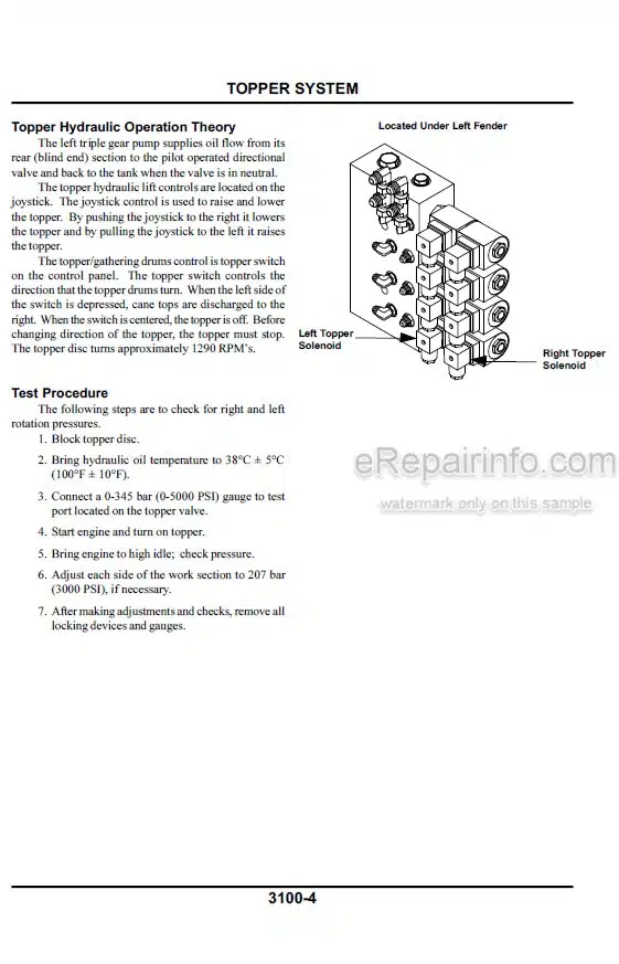
Topper Hydraulic Operation Theory
Test Procedure
Topper/Side Knives Electrical Schematic
Basecutter Fin and Knock Down and Front Feed Roller Hydraulic Schematic
Topper (Track and Wheel) Hydraulic Schematic
All Functions on Topper Do Not Operate — Whole or Shredder
All Functions on Topper
Do Not Operate — Whole or Shredder (Continued)
All Topper Functions Do Not Operate — Whole or Shredder
—CROP DIVIDER SYSTEM
Crop Divider Theory of Operation
Crop Divider Electrical Theory of Operation
Crop Divider Hydraulic Theory of Operation
Crop Divider Specifications
Crop Divider Control Operation
Test Procedure
Side Knife Theory of Operation
Side Knife Electrical Theory of Operation
Side Knife Hydraulic Theory of Operation
Side Knife Specifications
Side Knife Control Operation
Test Procedure
Crop Divider Electrical Schematic
Crop Divider Hydraulic Schematic
Crop Divider Sill Roller with 5 Ft Primary Extractor Hydraulic Schematic
Side Knives Control Circuit
Side Knives Control Circuit Electrical Schematic
Twin Crop Dividers Showing Slow or No Operation
Twin Crop Dividers Showing Slow or No Operation
Crop Dividers Showing Slow or No Operation
Crop Dividers Showing Slow No Operation
Crop Divider Lift Does Not Operate Properly
Crop Divider Lift Does Not Operate Properly
Side Knives Do Not Operate
Side Knives Do Not Operate
—BASECUTTER SYSTEM
Basecutter Theory of Operation
Basecutter Electrical System Operation
Hydraulic System Operation
Basecutter Specifications
Basecutter Control
Test Procedure: Basecutter Control Valve Main Relief
Basecutter and Chopper Electrical Schematic
Basecutter Fin Knock Down and Front Feed Roller Hydraulic Schematic
Basecutter Does Not Operate
Basecutter Does Not Operate
Basecutter Does Not Lift Correctly or Leaks Down — Track
Basecutter Does Not Lift Correctly or Leaks Down — Wheel
—FEED ROLLER SYSTEM
Description
Feed Roller Circuit Relief
Feed Roller Specifications
Feed Roller Control Operation
Buttlifter Theory of Operation
Front Feed Roller Test Procedure
Rear Feed Roller Test Procedure
Power Finned Roller Theory of Operation
Power Finned Roller Electrical System Operation
Power Finned Roller Hydraulic System Operation
Power Finned Roller Specifications
Power Finned Roller Control
Power Finned Roller Test Procedure
Feed Roller Hydraulic Schematic
Rear Set Feed Rollers) Forward/Reverse and Billet Selector Do Not Operate or Operate Slowly [EC]
Rear Set Feed Rollers Forward/Reverse and Billet Selector
Do Not Operate or Operate Slowly
Feed Rollers Forward/Reverse Do Not Operate and Chopper Blades Operate
Power Knockdown Feed Rollers have Slow or No Operation and other Basecutter Functions Operate [EC]
Power Knockdown Feed Roller has Slow or No Operation other Basecutter Functions Operate
Power Finned Roller Do Not Operate and other Basecutter Functions Operate
—CHOPPER SYSTEM
Chopper Theory of Operation
Chopper Electrical System Operation
Chopper Hydraulic System Operation
Chopper Specifications Control
Set Chopper Shaft Timing (Pinch)
Chopper Test Procedure
Basecutter and Chopper Electrical Schematic
Chopper and Feed Roller Hydraulic Schematic
Chopper Blades Show Slow or No Operation [EC]
Chopper Blades Show Slow or No Operation
—PRIMARY EXTRACTOR SYSTEM
Fixed Primary Extractor
Theory of Operation
Hydraulic System Operation
Electrical System Operation
Specifications
Control Operation
Primary Extractor Theory of Operation
Hydraulic System Operation
Direct Drive Variable Primary Extractor (FIVE FOOT)
Specifications
Control Operation
Shaft Drive Primary Extractor Theory of Operation
Hydraulic System Operation
Shaft Drive Variable Primary Extractor (FOUR FOOT)
Specifications
Control Operation
Primary Extractor Tachometer Electrical Schematic
Fixed Primary Extractor Electrical Schematic
Shaft Drive Primary Extractor (Four Foot) Hydraulic Schematic
Variable Direct Drive Primary Extractor (Five Foot) Hydraulic Schematic
Fixed Speed Primary Extractor Hydraulic Schematic
Fixed Speed Primary Extractor Does Not Operate
Direct Drive Variable Primary Extractor (5 Ft) Shows Slow or No Operation
Shaft Drive Variable Primary Extractor (4 Ft) Shows Slow or No Operation
—ELEVATOR SYSTEM
Elevator System On/Off and Forward/Reverse
Elevator System Up/Down Electrical System Operation
Secondary Extractor Electrical System Operation
Hood Rotate Extractor Electrical System Operation
Bin Flap Extractor Electrical System Operation
Hydraulic Theory of Operation
Elevator Control Electrical Schematic
Elevator Controls Hydraulic Schematic
Elevator Drive and Secondary Extractor Hydraulic Schematic
Elevator Forward Does Not Engage Other Elevator Functions Operate
Elevator Forward Does Not Engage Other Elevator Functions Operate
Momentary Elevator Forward/Reverse Does Not Engage
All Other Elevator Functions Operate
Momentary Elevator Forward/Reverse Does Not Operate
All Other Elevator Functions Operate
Elevator Lowers But Does Not Raise
Elevator Lowers But Does Not Raise
Elevator Raises But Does Not Lower
Elevator Raises But Does Not Lower
Secondary Hood Rotate Does Not Operate
Secondary Hood Rotate Does Not Operate
Secondary Extractor Fan Having Slow or No Operation
Bin Flap Does Not Operate
What you get
You will receive PDF file with high-quality manual on your email immediately after the payment.


Reviews
There are no reviews yet