


Factory Technical Manual For John Deere Cameco Chopper Combine. Manual Contains Illustrations, Instructions, Diagrams For Step By Step Remove And Install, Assembly And Disassembly, Service, Inspection, Repair, Troubleshooting, Tune-Ups.
Format: PDF
Language: English
Pages: 372
Searchable: Yes
Model
John Deere Comeco Chopper Combine
CH2500
Contents
-SAFETY RECOMMENDATIONS
Safety and You
Operation Safety
Service Safety
Safety in Your Service Area
Safety when Cleaning or Storing
Safety Nevers
Recognize Safety Information
Understand Signal Words
Follow Safety Instructions
Protect Bystanders
Use Handles and Steps
Prevent Machine Runaway
Avoid Exhaust Fumes
Keep Riders off Machine
Handle Fuel Safely—Avoid Fires
Safely Service Accumulator
Safely Service Cooling System
Prepare For Emergencies
Wear Protective Clothing
Use Safety Lights and Devices
Use Cylinder Safety Stops
Practice Safe Maintenance
Avoid High Pressure Fluids
Use Caution on Hillsides
Stopping and Parking
Service Tires Safely
Transport Combine Safely
Avoid Electrical Power Lines
Keep Hands Away From Knives
Avoid Contact with Moving Parts
Dispose of Waste Properly
Fire Prevention
Safety Recommendations
Combine Safety
-GENERAL SPECIFICATIONS
250 HP Specifications
250 HP Description
250 HP Preliminary Service Intervals
250 HP Common Engine Wear Parts
270 HP Specifications
270 HP Description
270 HP Preliminary Service Intervals
270 HP Common Engine Wear Parts
325 HP Specifications
325 HP Description
325 HP Preliminary Service Intervals
325 HP Common Engine Wear Parts
Specifications
Description
Preliminary Service Intervals
Common Engine Wear Parts
Standard Efficiency Hydraulic
Transmission—Track
Varitorq Transmission—Wheel
Oil Cooler Fan Motor
Steering Circuit—Wheel
Cylinder Control Circuit
Topper—Whole Top
Topper—Shredder
Topper—Collectors
Basecutter—2268 L/Min (250 HP, 60 GPM)
Basecutter—3024 L/Min (80 GPM)
Crop Dividers
Power Feed Roller—Low Basecutter
Power Feed Roller—High Basecutter
Chopper Drums
Chopper Drums—250 HP, 60 GPM
Feed Roller Oil Division
Front Feed Roller Set
Feed Roller—A1, A2, B1, and BL (Buttlifter)
Rear Feed Roller Set
Feed Roller—B2
Feed Roller—A3, A4, A5, B3, B4, and B5
Fixed Primary Extractor
Variable Primary Extractor
Secondary Extractor
Elevator
Elevator Functions
Secondary Extractor
-GENERAL CAPACITIES
Combine Capacities
Tire Inflation Pressure
-TORQUE SPECIFICATIONS
Suggested Torque Values For Grades
Conversion Factors
-FLUID RECOMMENDATIONS
Caterpillar Engine Coolant Requirements
Caterpillar Antifreeze
Engine Coolant Requirements
John Deere Coolant
John Deere Cool-Gard
Caterpillar Water
Caterpillar Conditioners
John Deere Antifreeze/Summer Coolant
John Deere Engine Coolant Requirements
Hydraulic Fluid (World)
Hydraulic Fluid (Australia)
Diesel Fuel
Engine Oil (Caterpillar)
Engine Break-in Oil (John Deere)
Diesel Engine Oil
Gear Oil
Gear Oil—Final Drive
Grease
—GENERAL INFORMATION
Straight 0-Ring Boss Fittings
Angled O-Ring Boss Fittings
37° Flare Cone Fittings
Hex Flats Recommended Rotation
Four Bolt Flange Fittings
Flange Metric Bolt Torque Chart
Flange SAE Bolt Torque Chart
Conversions
Weight Measure
Length Measure
Metric Measurements
Metric to English
English to Metric
Multiplication Factors
Temperature Conversion Chart
Conversion Formulas
Recommended Supplies
Hydraulic Gauge Kit
Specialty Tools and Part Numbers
—SERVICE POINTS
Combine Component Locations
Combine Service Point Locations
Combine Grease Point Locations
Grease Point Locations
—HYDROSTATIC TRANSMISSION
Hydrostatic Pump
Manual and Electrical Displacement Control
Suggested Tools And Supplies
General Repair Instructions
Displacement Control Replacement
Orifice Check Valve Replacement
Charge Pressure Relief Valve Replacement
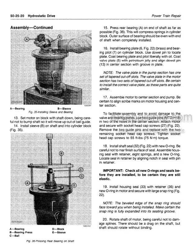
Shaft Seal Replacement
Multifunction Valve Cartridge
Charge Pump Disassembly
Charge Pump Reassembly
Variable Displacement Motor (Wheel)
Shaft Seal Disassembly
Inspect
Assembly
About Servicing The Motor
Cartridge Disassembly
Housing Disassembly
Shaft Assembly
Piston Ring
Bearing Plate, Valve Segment, and Cylinder
4-Way Valve and Feedback Springs
Housing Assembly
Housing Assembly
Fixed Displacement Motor (Track)
Cartridge Assembly
Piston Rings
Cylinder Block Assembly
End Cap to Main Housing Assembly
Track Fixed Displacement Motor Disassembly
Variable Displacement Motor
Cleanliness
Disassembly
Assembly
—MAIN HYDRAULIC SYSTEM
Multiple Gear Pump
World Multiple Gear Pump
World Multiple Gear Pump (Piggyback)
Multiple Gear Pump Repair
Suggested Tools
Repair Precautions
Bushing Removal Tool
Seal Removal Tool
Bushing Installation Tool
Special Steel Sleeve
Seal Installation Tool
Disassembly
Clean and Inspect
Assembly
Start Up Procedure
Recommended Test Procedure
Triple Vane Pump
General Repair
Pump Disassembly
Cartridge Kit Disassembly
Clean and Inspect
Before Assembly
Cartridge Kit Assembly
Pump Assembly
Pump Not Delivering Fluid
Insufficient Pressure Built-Up
Pump Making Noise
Five Bank Directional Valve
Suggested Tools
External Relief Settings
Overhaul
Valve Bank Disassembly
Spool Disassembly
Cleaning, Inspection, And Repair
Assembly
Spool Assembly—Spring Centered
Valve Section Assembly
Valve Bank Assembly
Section Disassembly
Preparation of Parts
Section Assembly
Relief Valve
Troubleshooting
Erratic Pressure
Low or No Pressure
Plug Vent Connection
Excessive Noise or Chatter
Repair
Necessary Tools
Removal
Disassembly
Clean And Inspect
Assembly
Troubleshooting
Erratic Pressure
Low or No Pressure
Plug Vent Connection
Excessive Noise or Chatter
Repair
Necessary Tools
Removal
—STEERING SYSTEM
Priority Valve
Main Spool Repair
Relief Valve Adjustment
Relief Valve Repair
Priority Valve
Main Spool Repair
Relief Valve Adjustment
Relief Valve Repair
Steering Valve
Suggested Tools
Disassembly
Clean and Inspect
Reassembly
Troubleshooting
Steering Cylinder
Tools and Supplies
Disassembly
Clean and Inspect
Assembly
Steering Linkage
Steering Bellcrank
Disassembly
Clean and Inspect
Assembly
Toe-in Adjustment
—OPERATOR’S STATION
Window Replacement
Operator’s Station
Cab Glass Replacement
Front Glass Removal
Front Glass Installation
Flat Glass Removal
Flat Glass Installation
Upper Rh Glass Removal
Upper Rh Glass Installation
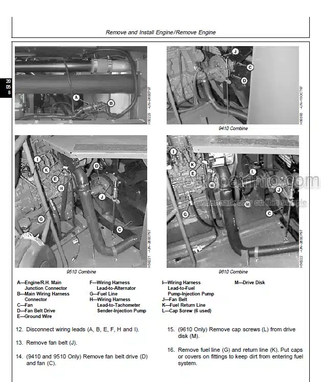
—ENGINE AND AUXILIARY SYSTEM
Pump Drive
Pump Drive Removal
Disassembly
Clean and Inspect
Assembly
—FINAL DRIVE
Final Drive
Suggested Tools
Disassembly
Install Spindle Nut
Assembly
Start-Up After Repair
Maintenance
Oil Change Interval—Gear Drive
—WHEEL AND TRACK
Right Side View
Track Assembly
Track Alignment
Roller Lubrication
Idler Lubrication
Track Shoe Tightening
Track Shoe Inspection Torque
Sprocket Tightening
Rear Axle Maintenance
Track Adjustment
Front Idlers
Lubrication
Identifying Master Link For Chain Removal
Recoil Spring Repair
Recoil Spring Adjustment
Specifications
Link Rail Wear
Link Rail Measurement
Rebuildability
Link Percentage Worn Chart
Sealed Track Bushings & Pins
Bushing and Pin Wear
Wear Measurement
Wear Limits—Service and Destruction
Track Bushing Allowable Wear Chart
Internal Pitch Wear
Measurement Technique
Detrimental Effects of Excessive Pitch
Allowable Wear
Internal Pitch Percentage Worn Chart
Track Rollers
Track Roller Lubrication
Seal Assembly
Specifications
Carrier Roller
Carrier Roller Lubrication
Carrier Roller Assembly
Specifications
Sprocket Wear Patterns
Sprocket Replacement
Tip Gouged
Rolling Undercarriage
Roller Wear Diagnosis
How To Measure Roller Wear
Specifications
Carrier Roller Percentage Worn
Track Roller Percentage Worn
Rolling Undercarriage
Flange To Boss Measurement
Idler Tread Wear Measurement
Swapping Idlers
Check Idler Flange Wear
Flange Top Wear
Flange Side Wear
Idlers Percentage Worn Chart
Track Shoe Problems
Grouser Wear Measurement
Wear Limits—Service and Destruction
Grouser Wear
Plate Wear and Leading/Trailing Edge Wear
Bolt Hole Wallowing Out
Self-Locking Track Nut
Sprocket Chain Roller Alignment
Wheel Assembly
Remove And Replace Front Wheel Bearings
Suggested Tools
Remove Rear Wheel Assembly
To Remove And Mount Tire
Install Wheel Assembly
Tire Pressure Specifications
—TOPPER SYSTEM
Collector, Crop Divider, Feed Roller, and Elevator Motor
Suggested Tools
Collector Motor
Disassembly
Clean and Inspect
Assembly
Topper
Topper Repair
Collector Drum and Motor Removal
Topper Assembly Removal
Clean and Inspect
Drum and Topper Assembly
Shredder Topper
Topper Repair
Collector Drum and Motor Removal
Topper Assembly Removal
Clean and Inspect
Drum and Topper Assembly
Scroll Cylinder
Suggested Tools
Disassembly
Clean And Inspect
Assembly
Gear Motor
Gear Motor Repair
Suggested Tools
Repair Precautions
Bushing Removal Tool
Seal Removal Tool
Bushing Installation Tool
Disassembly
Clean And Inspect
Assembly
Start Up Procedure
Recommended Test Procedure
—CROP DIVIDER SYSTEM
Crop Divider
Crop Divider Removal
Disassembly
Clean and Inspect
Assembly
Crop Divider Shoe Assembly
Crop Divider Shoe Removal
Twin Crop Divider
Twin Crop Divider Removal
Clean and Inspect
Assembly
—BASECUTTER SYSTEM
Basecutter
Basecutter Gearbox
Gearbox Removal
Gearbox Installation
Gearbox Disassembly
Leg Shaft Removal
Pinion Gear Removal
Clean and Inspect
Before Assembly
Gearbox Assembly
Pinion Installation
Bearing Installation
Leg Shaft Preassembly
Assembly and Timing
Timing Procedure (New Parts)
Low Drive Basecutter Gearbox
Basecutter Gearbox
Removal
Disassembly
Clean and Inspect
Assembly
Set Preload
Adjust Clutch Overload Protection
Setting Procedure
Inspection
Accumulator
Maintenance
Pre-Charge Checking Procedure
Removal
Disassembly
Clean and Inspect
Assembly
Directional Valve
Work Section
Introduction
Removal
Disassembly
Spool Section Disassembly
Clean and Inspect
Assembly
Main Relief Valve
Work Port Relief Valve
Basecutter Lift Cylinder (Wheel)
Disassembly
Clean and Inspect
Reassembly
Basecutter Lift Cylinder (Track)
Suggested Tools
Disassembly
Clean and Inspect
Reassembly
—FEED ROLLER SYSTEM
Power Finned Roller
Removal
Disassembly
Clean And Inspect
Assembly
Buttlifter Roller (BL)
Repair
Clean and Inspect
Assembly
Bottom Feed Roller (B1)
Repair
Clean and Inspect
Assembly
Bottom Feed Roller (B2) & (B5)
Repair
Clean and Inspect
Assembly
Bottom Feed Roller (B3) & (B4)
Repair
Clean and Inspect
Assembly
Feed Roller (A1)
Repair
Clean and Inspect
Assembly
Top Floating Feed Roller (A2, A3, A4, & A5)
Repair
Clean and Inspect
Assembly
—CHOPPER SYSTEM
Chopper Gearbox
Remove
Clean and Inspect
Chopper Box Pre Assembly
Chopper Hub
Chopper Hubs Pre Assembly and Installed
Chopper Drums
Chopper Drum Assembly
Timing Gear Assembly and Adjustment
Differential Chopper Timing Gear
Slip Clutch
Disassembly
Assembly (Flywheel & Slip Clutch)
Field Setting of Slip Clutch
Clean and Close Box
Assembly Chopper Motors
Assembly Chopper Deflector Shields
Install and Adjust Sill Plate
Chopper System—Six Blade
Billet Length—Six Blade
Chopper System—Four Blade
Billet Length—Four Blade
Chopper System—Eight Blade
Chopper Blades
Slip Clutch Adjustment
Chopper Gearbox Lubrication
Gearbox Oil Capacities
Six Blade
Four Blade
Chopper System
Chopper System Operation
Adjusting Chopper Blade Timing-Pinch
Chopper System
Differential Chopper Timing
Chopper Motor—12 Inch
Suggested Tools
Disassembly
Clean and Inspect
Assembly
Chopper Motor—15 Inch
Suggested Tools
Disassembly
Reassembly
—CLEANING SYSTEM
Hydraulic Primary Extractor
Primary Extractor Tachometer
Elevator Boom
Fan Assy
Installing The Hub To Motor Shaft
Installing Fan Blades, Doubler Plates and Backing Plate
Safety Start Up
Fan Mounting-Primary Extractor
Disassembly
Preassembly Fan Hub and Blades
Preassembly Primary Extractor
Direct Drive Motor
Install Primary Extractor Direct Drive Motor
Into Primary Extractor Hood
Install Fan Hub Assembly
Sill Roller Assembly
Disassembly
Assembly
Variable Primary Extractor Pump
Manual Displacement Control
Suggested Tools
Multi-Function Valve Adjustment
Stroke Limiter Adjustment!
Charge Relief Adjustment
Minor Repair
General Repair
Manual Displacement Control Replacement
Orifice Check Valve Replacement
Charge Pressure Relief Valve Replacement
Shaft Seal Replacement
Multi-Function Valve Cartridge
Replacement (2 per pump)
Charge Pump Disassembly
Reassembly
Wiper Motor
Suggested Tools
Disassembly
Clean and Inspect
Assembly
Primary Extractor Motor
Tools Required
Disassembly Shaft Seal
Disassembly End Cover with Integral Shuttle and Low Pressure Relief Valve
Disassembly of End Cover
Disassembly of Rotating Group
Reassembly
Reassembly of Shaft Seal
Reassembly of End Cover
Shaft Bearing Cone Driver (End Cover end)
Low Clearance Bearing Puller
—ELEVATOR SYSTEM
Standard Capacity Elevator System
Elevator Group
Chain Adjustment
Changing Chain and Sprockets
Headshaft Repair
Disassembly
Assembly
Chain Removal On Repair
High Capacity Elevator System
High Capacity Elevator Drive
Manual Chain Adjustment For
High Capacity Elevators
High Capacity Elevator
Grease Cylinder Elevator Chain Adjustment Elevator Swing Table
Description
Removal
Clean and Inspect
Assembly
Elevator Swing Table
Description
Removal
Clean and Inspect
Assembly
Elevator Swing Cylinder
Disassembly
Clean and Inspect
Guide Rod Seal Installation
Piston Seal Installation
Cylinder Assembly
Elevator Lift Cylinder
Disassembly
Clean and Inspect
Piston Seal Installation
Cylinder Assembly
What you get
You will receive PDF file with high-quality manual on your email immediately after the payment.


Reviews
There are no reviews yet.