


Factory Technical Manual For John Deere Garden Tractor. Manual Contains Illustrations, Instructions, Diagrams For Step By Step Remove And Install, Assembly And Disassembly, Service, Inspection, Repair, Troubleshooting, Tune-Ups.
Format: PDF
Language: English
Pages: 366
Number: TM1974 (march 2003)
Searchable: Yes
Wiring Diagrams: Yes
Hydraulic Diagrams: Yes
Model
John Deere Garden Tractor
GX355
Contents
-SAFETY
Recognize Safety Information
Understand Signal Words
Replace Safety Signs
Be Prepared for Emergencies
Use Care in Handling and Servicing Batteries
Use Care Around High-Pressure Fluid Lines
Use Safe Service Procedures
Service Tires Safely
Service Cooling System Safely
Handle Chemical Products Safely
Dispose of Waste Properly
Live with Safety
-SPECIFICATIONS AND INFORMATION
Metric Fastener Torque Values
Metric Fastener Torque Values -Grade
Inch Fastener Torque Values
Face Seal Fittings with Inch Stud Ends Torque
Face Seal Fittings with Metric Stud Ends
Torque
O-Ring Face Seal Fittings
O-Ring Boss Fittings
Diesel Fuel
Diesel Fuel Lubricity
Diesel Fuel Storage
Engine Oil
Engine Break-in Oil
Alternative Lubricants
Synthetic Lubricants
Lubricant Storage
Mixing of Lubricants
Chassis Grease
Transaxle Oil
Engine Coolant
Operating in Warm Temperature Climates
Flush and Service Cooling System
Disposing of Coolant
Engine Coolant Drain Interval
Machine Product Identification Number
Engine Serial Number Location
Transmission Serial Number Location
-ENGINE
Engine Specifications
Fuel System
Tests and Adjustments Specifications
Repair Specifications
Torque Specifications (Aluminum Block)
Special Tools
Other Materials
Engine Components
Hood Switch
Lubrication System Operation
Cooling System Operation
Fuel / Air System Operation
Engine System
Oil Pressure Test
Cylinder Compression Test
Throttle Cable Adjustment
Slow Idle Speed Adjustment
Fast Idle Speed Adjustment
Torque Capsule Adjustment
Valve Clearance Inspection and Adjustment
Fuel Injection Pump Timing Adjustment
Radiator Cap Pressure Test
Radiator Bubble Test
Cooling System Pressure Test
Thermostat Opening Test
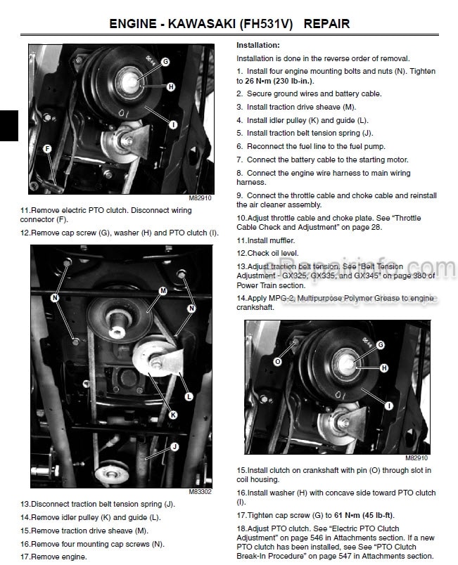
Engine Removal and Installation
Engine Mounts and Isolators: Position and
Torques
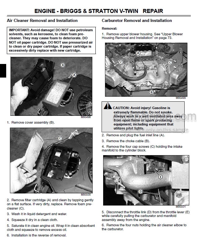
Air Filter Removal and Installation
Muffler Removal and Installation
Intake Manifold Removal and Installation
Oil Pressure Sensor Removal and Installation
Thermostat Removal And Installation 45
Coolant Temperature Sensor Removal and Installation
Radiator Removal And Installation
Fuel Shut-Off Solenoid Removal and Installation
Fuel Hoses Removal And Installation
Fuel Pump Removal And Installation
Fuel Filter Removal And Installation
Fuel Injectors Removal and Installation
Fuel Injectors Tests
Injection Pump Assembly Removal and Installation
Governor Assembly Removal and Installation
Fan/Flywheel Removal And Installation
Rocker Arm Covers Removal and Installation
Rocker Arms Removal And Installation
Number 1 Cylinder Head Removal and Installation
Number 2 Cylinder Head Removal and Installation
Glow Plugs Removal and Installation
Cylinder Head and Valves Disassembly and Inspection
Cylinder Head and Valves Assembly
Crankcase Breather Removal And Installation
Crankcase Cover Removal and Installation
Water Pump Removal and Installation
Oil Pump Removal and Installation
Camshaft, Valve Lifters, and Injection Pump
Lifters Removal and Installation
Camshaft, Valve Lifters, and Injection Pump
Lifters Inspection
Piston and Connecting Rod Removal and Installation
Crankshaft Removal and Installation
Stator Removal And Installation
Starter Solenoid Removal and Installation
Starter Motor Removal and Installation
Starter Motor Disassembly and Assembly
-ELECTRICAL
Reading Electrical Schematics
Theory of Operation Information
Diagnostic Information
Wire Color Abbreviation Chart
Common Circuit Tests
Conductors for 12 Volt Circuits
General Specifications
Special or Required Tools
Schematic and Wiring Harness Legend
Component Location
Main Electrical Schematic
Main Wiring Harness
Main Wiring Harness Color Codes
Additional Wiring Harnesses
Unswitched Power Circuit Operation
Unswitched Power Circuit Schematic
Unswitched Power Circuit Diagnosis
Switched Power Circuit #1 Operation
Switched Power Circuit #1 Schematic
Switched Power Circuit #1 Diagnosis
Switched Power Circuit #2 Operation
Switched Power Circuit #2 Schematic
Switched Power Circuit #2 Diagnosis
Starting Circuit Operation
Starting Circuit Schematic
Starting Circuit Diagnosis1
Fuel Shut-Off & Fuel Pump Circuit Operation
Fuel Shut-Off & Fuel Pump Circuit Schematic
Fuel Shut-Off & Fuel Pump Circuit Diagnosis
Charging Circuit Operation
Charging Circuit Schematic
Charging Circuit Diagnosis
PTO Circuit Operation
PTO Circuit Schematic
PTO Circuit Diagnosis
RIO Circuit Operation
RIO Circuit Schematic
RIO Circuit Diagnosis
Coolant Temperature Sensor Circuit Operation
Coolant Temperature Sensor Circuit Schematic
Coolant Temperature Sensor Circuit Diagnosis
Air Restriction Indicator Circuit Operation
Air Restriction Indicator Circuit Schematic
Air Restriction Indicator Diagnosis
Oil Pressure & Low Fuel Sensor Circuit Operation
Oil Pressure & Low Fuel Sensor Circuit Schematic
Oil Pressure & Low Fuel Sensor Diagnosis
Headlight & Hour Meter Circuit Operation
Headlight & Hour Meter Circuit Schematic
Headlight & Hour Meter Circuit Diagnosis
Common Circuit Tests
Ground Circuit Test
Battery Test
Charge Battery
Battery Load Test
Regulated Voltage Test
Unregulated Voltage Test
Regulated Amperage Test
Starting Motor Solenoid Test
Starting Motor No-Load Amperage Draw and RPM Test
Starting Motor Loaded Amperage Draw Test
Hood Switch Connector Jumper Wire Test
Fuel Shut-Off Solenoid Test
Seat Switch Test
Brake Switch Test
PTO/RIO Switch Test
RIO Switch Test
PTO Clutch Test
PTO Clutch Adjustment
Headlight Switch Test
Engine Oil Pressure Sensor Test
Glow Plug Test
Low Fuel Level Sensor Test
Air Restriction Indicator Sensor Test
V1 and V2 Diodes Test
Hour Meter Test
Fuel Pump Tests
Key Switch Test
Coolant Temperature Switch Test
Starting Motor and Starting Motor Solenoid
PTO Clutch
Connector Body – Blade Terminals
METRIPACK, Connectors
-POWER TRAIN
Hydrostatic Transaxle
Adjustment Specifications
Repair Specifications
Torque Specifications
Other Materials
Transaxle Case Halves
Charge Pump
Piston Pump
Motor
Reduction Gears, Differential, and Axles
Swash Plate and Neutral Centering Assembly
Transaxle Brake
Center Case Assembly
Belt Drive and Idlers
Brake Pedal and Linkage
Forward and Reverse Pedals and Linkage (Exploded View)
Controls and Linkage Operation
Foot Controls
Brake Linkage
Hydrostatic System Operation
Gear Power Flow
Machine Will Not Move Forward Or Reverse
Noisy Operation
Machine Creeps
Machine Moves In One Direction Only
Erratic Speed
Machine Does Not Achieve Full Ground Speed
Park Brake Does Not Hold Machine On Hill
Brake Switch Will Not Engage
Hydrostatic Transaxle Bleeding Procedure
Neutral Creep Adjustment
Forward and Reverse Pedal Height Adjustment
Brake Linkage Adjustment
Belt Tension Adjustment
Traction Drive Belt Removal and Installation
Traction Drive Belt Tensioner Assembly
Control Pedals and Linkage
Intermediate Shaft
Brake Pedal and Linkage
Brake Rod Removal and Installation
Transaxle Removal and Installation
Case Disassembly
Final Drive and Axle Removal
Brake Removal
Rotating Group Removal
Control Shaft Removal
Control Shaft Disassembly
Oil Filler Tube Removal
Shock Absorber Removal
Freewheeling Control Shaft Removal
Center Case Disassembly
Transaxle Assembly
Freewheeling Control Shaft Installation
Shock Absorber Installation
Oil Filler Tube Installation
Control Shaft Assembly
Control Shaft Installation
Rotating Group Assembly
Brake Installation
Charge Pump Installation
Final Drive and Axle Installation
Case Assembly
-HYDRAULICS
Tests and Adjustments Specifications
Repair Specifications
Special Tools
Special Materials
Hydraulic Lift System Components
Lift Lever and Linkage
Mower Deck Lift Linkage
Hydraulic Schematic
Hydraulic Lift System Operation
Noise From Transmission When Using Hydraulics
Excessive Attachment Drop With Control Valve
In Neutral
Hydraulic Lift Slow Or No Lift Capacity
Hydraulic Lift Will Not Work
Hydraulic Lift Oil Flow and Pressure Test
Hydraulic Lift Control Valve
Hydraulic Lift Cylinder Removal and Installation
Lift Lever Removal And Installation
Lift Linkage Inspection
Hydraulic In-Line Filter Removal and Installation
-STEERING
Tests and Adjustments Specifications
Torque Specifications
Special Tools
Other Materials
Steering System Components
Steering Valve and System Operation 280
Tilt Steering Operation
Hydraulic System Checks
Steers Hard or No Steering In Both Directions
Steers Hard or No Steering In One Direction
Steering Pulls In One Direction
Steering Wheel Tilt Assembly Will Not Move
Steering Wheel Creeps
Steering Shimmy Or Vibration
Noise During Turn
Slow Steering Responses
Steering System Oil Flow And Pressure Tests
Steering System Leakage Test
Steering Valve Leakage Test
Steering Cylinder Leakage Test
Toe-In Adjustment
Steering Tilt Assembly
Steering Valve and Column
Steering Cylinder
-BRAKES
Brake Pedal and Linkage
External Brake Linkage
Transaxle Brake Operation
Machine Will Not Move In Forward Or Reverse
Brakes Do Not Engage When Pedal Depressed
Parking Brake Does Not Hold Machine On Hill
Noisy Operation
Erratic Speed
Machine Does Not Achieve Full Ground Speed
Machine Will Not Move In Forward Direction Or Is Slow In Forward
Machine Is Slow In Reverse
Neutral Start Switch Does Not Engage When Pressing Brake Pedal
Engine Can Be Started Without Depressing Brake Pedal
Brake Linkage Test And Adjustment
Brake Assembly
-ATTACHMENTS
Mower Deck Adjustment Specifications
Mower Deck Repair Specifications
Special Tools
48 – Inch Convertible Mower Deck
54 – Inch Convertible Mower Deck
Mower Decks Troubleshooting Chart
Mower Drive Checks
PTO Clutch Diagnosis
Mower Level Side-to-Side
Mower Level Front-To-Rear
Electric PTO Clutch Adjustment
Electric PTO Clutch Removal and Installation
PTO Clutch Break-In Procedure
48-Inch Convertible Mower Deck Removal and Installation
48-Inch Mower Drive Belt
48-Inch Deck Mower Blades
48-Inch Deck Spindles
48-Inch Deck Jack Sheave
Idlers
54-Inch Mower Deck Removal and Installation
-MISCELLANEOUS
Torque Specifications
Front Axle
Steering Spindles
Front Wheels
Rear Wheels
Engine Hood
Control / Dash Panel
Fender Deck and Tunnel Cover
Fuel Tank
What you get
You will receive PDF file with high-quality manual on your email immediately after the payment.


Reviews
There are no reviews yet.