Factory Service Manual For Kobelco Hydraulic Excavator and Mitsubishi Diesel Engine. Manual Contains Illustrations, Instructions, Diagrams For Step By Step Remove And Install, Assembly And Disassembly, Service, Inspection, Repair, Troubleshooting, Tune-Ups.
Format: PDF
Language: English
Pages: 1101
Number: S5YY0024E02 (September 2012)
Bookmarks: Yes
Searchable: Yes
Wiring Diagrams: Yes
Hydraulic Diagrams: Yes
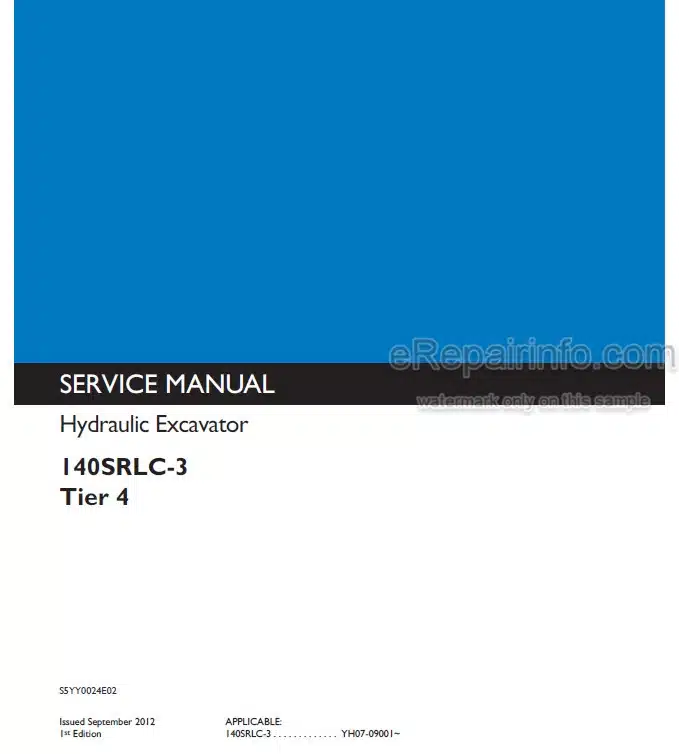
Model
Kobelco Hydraulic Excavator
140SRLC-3
Tier 4
Mitsubishi Diesel Engine
DO4EG-TAA
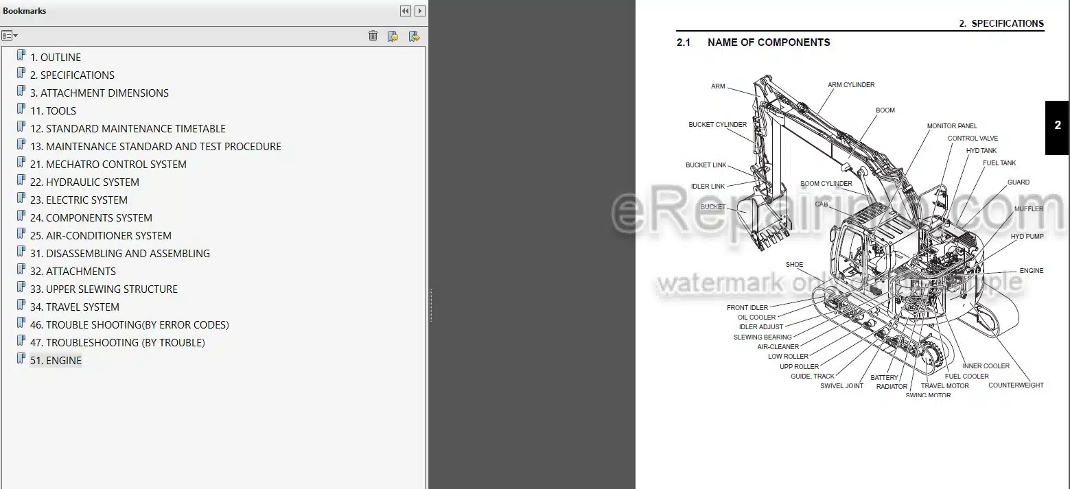
Contents
1.KOBELCO 140SRLC TIER 4 SERVICE MANUAL HYDRAULIC EXCAVATOR.
2.MITSUBISHI DO4EG-TAA SERVICE MANUAL DIESEL ENGINE.
1.KOBELCO 140SRLC TIER 4 SERVICE MANUAL HYDRAULIC EXCAVATOR.
-OUTLINE
General Precautions For Making Repairs
International Unit System
-SPECIFICATIONS
Name Of Components
General Dimensions
Weight Of Components
Transportation
Specifications And Performance
Type Of Crawler
Type Of Bucket
Combinations Of Attachment
Engine Specification
-ATTACHMENT DIMENSIONS
Boom
Arm
Bucket
-TOOLS
Tightening Torques For Capscrewsand Nuts
Screw Size
Tightening Torque For Hose And Fitting
Tightening Torques For Nuts And Sleeves
Plugs
Special Spanner For Tube
Special Tools
Application Of Screw Locking Compound And Sealing Compound
Suction Stopper
Counterweight Lifting Jig
Tool For Pulling Out Of Boom Mounting Pin
Upper Frame Lifting Jig
Engine Mounting Pedestal
Track Spring Set Jig
-STANDARD MAINTENANCE TIMETABLE
Standard Working Time Table For The Maintenance Of Excavator
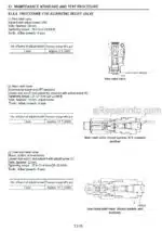
-MAINTENANCE STANDARD AND TEST PROCEDURE
How To Use Maintenance Standards And Precautions
Performance Inspection Standard Table
Measurement Of Engine Speed
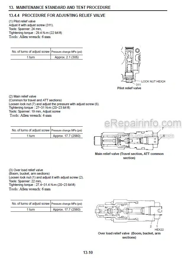
Measurement Of Hydraulic Pressure
Measuring Travel Performances
Measuring Swing Performances
Measuring Attachment Operating Performances
Measuring Performances Of Swing Bearing
Mechatro Controller
Exhaust Gas Post-Cleaning Device
-MECHATRO CONTROL SYSTEM
Summary Of Mechatro Control System
Mechatro Controller
-HYDRAULIC SYSTEM
Summary
Hydraulic Circuits And Components
Color Coding Standard For Hydraulic Circuits
Neutral Circuit
Travel Circuit
Bucket Circuit
Boom Circuit
Swing Circuit
Arm Circuit
Combined Circuit
Pressure Draining (Releasing) Circuit
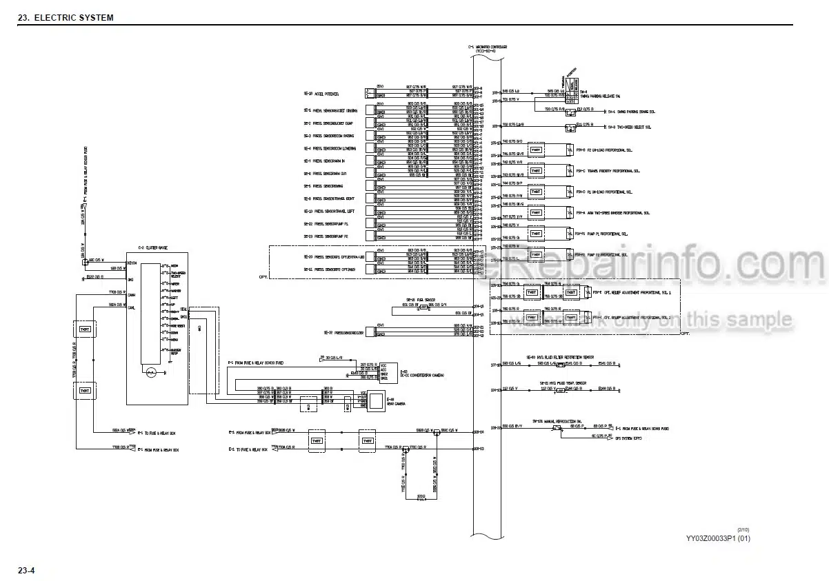
-ELECTRIC SYSTEM
Electric Circuit Diagram
Electrical Equipment
Harness
-COMPONENTS SYSTEM
Hydraulic Components
Electrical Equipment
-AIR-CONDITIONER SYSTEM
Basic System Of Air Conditioner (Hvac Air Conditioner)
Component And Construction
Piping
Function
Disassembly And Assembly
Charging Refrigerant
Electric Circuit
Troubleshooting
Self-Diagnosis
-DISASSEMBLING AND ASSEMBLING
Explaining Chapter Of Whole Disassembly & Assembly
-ATTACHMENTS
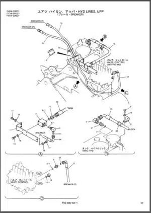
Removing And Installing
Disassembling And Assembling
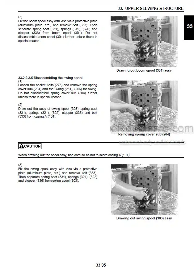
-UPPER SLEWING STRUCTURE
Removing And Installing
Disassembling And Assembling
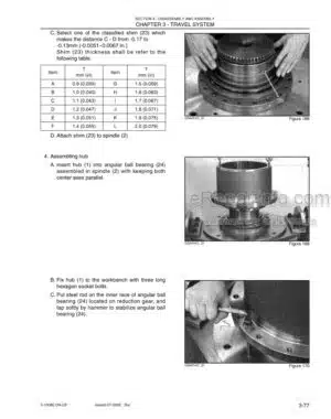
-TRAVEL SYSTEM
Removing And Installing
Removal And Installation Of Travel Motor Unit
-TROUBLESHOOTING(BY ERROR CODES)
Judgment Of Actual Thing At Site
Classification Of Failure And Troubleshooting
The Blown Fuse Of Mechatro Controller
Troubleshooting By Error Code
-TROUBLESHOOTING (BY TROUBLE)
Hydraulic System
Electric Systems
Engine Related Troubleshooting
-ENGINE
2.MITSUBISHI DO4EG-TAA SERVICE MANUAL DIESEL ENGINE.
-GENERAL
External View
Outline Of Systems
Engine Serial Number
Specifications
–SERVICE DATA
Maintenance Service Data
Tightening Torque Table
-SERVICE TOOLS
Special Tools
-OVERHAUL INSTRUCTIONS
Determining Overhaul Timing
Compression Pressure – Measure
-DISASSEMBLY OF BASIC ENGINE
Cylinder Heads and Valve Mechanisms – Disassemble and Inspect
Rear Mechanism – Disassemble and Inspect
Front Mechanism – Disassemble and Inspect
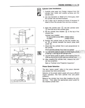
Piston, Connecting rod, Crankshaft and Crankcase – Disassemble and Inspect
-INSPECTION AND REPAIR OF BASIC ENGINE
Cylinder Head and Valve Mechanism – Inspect and Repair
Rear Mechanism – Inspect and Repair
Front Mechanism – Inspect and Repair
Piston and Connecting Rod – Inspect and Repair
Crankcase and Crankshaft – Inspect and Repair
-ASSEMBLY OF BASIC ENGINE
Piston, Connecting rod, Crankshaft and Crankcase – Assemble
Front Mechanism – Assemble
Rear Mechanism – Assemble
Cylinder Head and Valve Mechanism – Assemble
-FUEL SYSTEM
Environmental Condition to Disassemble and Assemble the Fuel System
Fuel System – Remove
Common Rail Assembly – Disassemble and Inspect
Fuel System – Disassemble, Inspect and Assemble
High-Pressure Pump – Disassemble and Inspect
Fuel System – Install
-LUBRICATION SYSTEM
Lubrication System – Remove and Inspect
Lubrication System – Disassemble, Inspect and Assemble
Lubrication System – Install
-COOLING SYSTEM
Cooling System – Remove
Cooling System – Inspect
Cooling System – Install
-INLET AND EXHAUST SYSTEMS
Inlet and Exhaust Systems – Remove
Inlet and Exhaust Systems – Disassemble, Inspect and Assemble
Inlet and Exhaust Systems – Install
-ELECTRICAL SYSTEM
Electrical System – Remove and Inspect
Electrical System – Disassemble, Inspect and Assemble
Electrical System – Install
-ADJUSTMENT AND OPERATION
Engine – Adjust
Break-in Operation
Performance Test
Error Code Table
What you get
You will receive PDF file with high-quality manual on your email immediately after the payment.

Reviews
There are no reviews yet.