Factory Shop Manual For Kobelco Hydraulic Excavator; Mitsubishi Diesel Engine. Manual Contains Illustrations, Instructions, Diagrams For Step By Step Remove And Install, Assembly And Disassembly, Service, Inspection, Repair, Troubleshooting, Tune-Ups.
Format: PDF
Language: English
Pages: 1160
Number: 87364097 NA (July 2006)
Bookmarks: Yes
Wiring Diagrams: Yes
Hydraulic Diagrams: Yes
Model
Kobelco Hydraulic Excavator
SK250LC-6E
Mitsubishi Diesel Engine
6D34-T
Contents
1.KOBELCO SK250LC-6E SHOP MANUAL HYDRAULIC EXCAVATOR.
2.MITSUBISHI 6D34T-SHOP MANUAL DIESEL ENGINE.
1.KOBELCO SK250LC-6E SHOP MANUAL HYDRAULIC EXCAVATOR.
-CYCLE TIMES
Pre-Cycle Time Considerations
Cylinder Cycle Time Tests
Swing Speed Time Test
Travel Speed Time Test
-MAINTENANCE SPECIFICATIONS
Cylinder Drift
Swing Stopping
Swing Drift
Swing Bearing Up-Down (Vertical) Movement
Swing Bearing Side To Side (Horizontal) Movement
Swing Motor Oil Case Drain
Travel Motor Oil Case Drain
Travel Deviation
-HYDRAULIC SCHEMATICS
Symbolsand Components
Hydraulic Control System Logic
Troubleshooting Table
Hydraulic Schematic
-PRESSURE ADJUSTMENTS
Verification Of Engine Rpm
Pilot Circuit
Hydraulic Main Relief
Swing Circuit
Over Load Relief Valves
Measurement Of Additional Circuit Pressure Ports
-MECHATRONICS
Layout of Electric Components
Solenoid/Proportional V alve Block
Construction of Solenoid Valve
Proportional Valve for Control Valve
Pressure Sensors
Components Related to Engine
Left Hand Console
Right Hand Console
Components Related to Cab
Floorplate Wiring Info
Grounding Cable Attaching Position
Main Controller Assembly
Mechatronic Controller Connectors
Mechatronic Controller Assembly
Pin Out of Connectors CN11
Pin Out of Connectors CN12~13
Pin Out of Connectors CN14
Pin Out of Connectors CN15-16
Pin Out of Connectors CN17
Governor Motor (Stepping Motor)
Gauge Cluster
Multi Display Self Diagnostic
Engine Speed Sensor (Sei3)
Potentiometer (For Accel Dial, Se16)
Error Code History Diagnosis
Senice Diagnostic
Adjustment “A & B”
Adjustment ’‘A” – Mechatronic Controller
Procedure “B”
Fine Operating Adjustment Function
-ELECTRICAL SCHEMATICS
Electrical Schematic Symbols
Schematic Nomenclature
Electrical Schematics
-SPECIFICATIONS
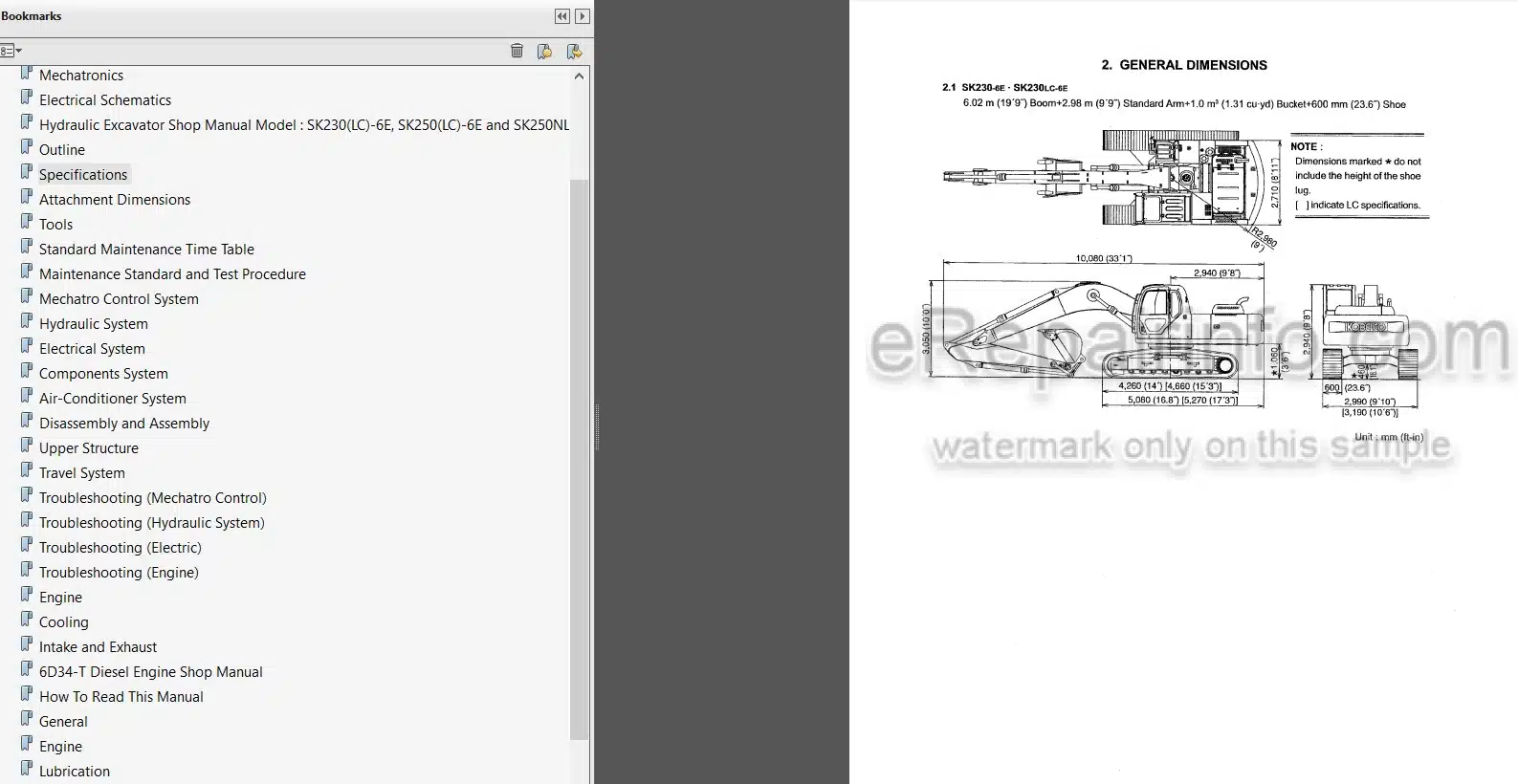
Outline
Specification
Attachment Dimension
-MAINTENACE
Tools
Standard Maintenance Time Schedule
Maintenance Standard And Test Procedure
-SYSTEM
Mechatro Control System
Hydraulic System
Electrical System
Components System
Air-Conditioner System
-DISASSEMBLY
Disassembling And Assembling
Attachment
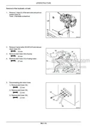
Upper Structure
Travel System
-TROUBLESHOOTING
Mechatro Control
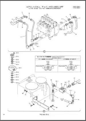
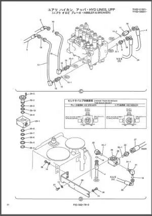
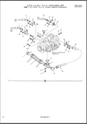
Hydraulic
Electrical
Engine
2.MITSUBISHI 6D34T-SHOP MANUAL DIESEL ENGINE.
-GENERAL
General Specifications
Engine Number, Name Plate And Caution Plate
Precautions For Maintenance Operation
Table Of Standard Tightening Torques
-ENGINE
Structure And Operation
Troubleshooting
On-Vehicle Inspection And Adjustment
Cylinder Head And Valve Mechanism
Timing Gears
Camshaft
Pistons, Connecting Rods, And Cylinder Liners
Flywheel
Crankshaft And Crankcase
-LUBRICATION
Specifications
Structure And Operation
Troubleshooting
On-Vehicle Inspection And Adjustment
Oil Pan, Oil Strainer, And Oil Jet
Oil Pump
Oil Cooler And Oil Filter
-FUEL AND ENGINE CONTROL
Specifications
Structure And Operation
Troubleshooting
On-Vehicle Inspection And Adjustment
Fuel Filter
Injection Pump
Injection Nozzle
-COOLING
Specifications
Structure And Operation
Troubleshooting
On-Vehicle Inspection And Adjustment
Cooling Fan, V-Belt, And Water Pump
Thermostat
-INTAKE AND EXHAUST
Specifications
Structure And Operation
Troubleshooting
Turbocharger
Intake Manifold
Exhaust Manifold
Intercooler
-ELECTRICAL SYSTEM
Specifications
Structure And Operation
Troubleshooting
On-Vehicle Inspection And Adjustment
Alternator
Starter
Preheater Circuit
Engine Starter Circuit
What you get
You will receive PDF file with high-quality manual on your email immediately after the payment.







Reviews
There are no reviews yet.