


Factory Shop Manual For Komatsu Engine. Manual Contains Illustrations, Instructions, Diagrams For Step By Step Remove And Install, Assembly And Disassembly, Service, Inspection, Repair, Troubleshooting, Tune-Ups.
Format: PDF
Language: English
Pages: 385
Number: SEN04211-03 (december 2007)
Bookmarks: Yes
Searchable: Yes
Wiring Diagrams: Yes
Model
Komatsu Engine
3D82AE
3D82AE-B
3D84E,
S3D84E
S3D84E-B
3D88E
3D88E-B
3D88E-U
4D84E
4D88E
4D88E-B
4D88E-U
4D94LE
4D98E
Contents
-INDEX AND FOREWORD
Index
Introduction
Applicable Machine Model And Serial Number
Safety Statements
Safety Precautions
-SPECIFICATION NAD TECHNICAL DATA
Component Identification
Function Of Major Engine Components
Main Electronic Control Components And Features
Function Of Cooling System Components
Diesel Fuel
Engine Oil
Engine Coolant
Specifications
Principal Engine Specifications
Engine Service Standards
Tightening Torques For Standard Bolts And Nuts
Abbreviations And Symbols
Unit Conversions
-TESTING AND ADJUSTING
Before You Begin Servicing
Introduction
Periodic Maintenance Schedule
Periodic Maintenance Procedures
Before You Begin Servicing
Introduction
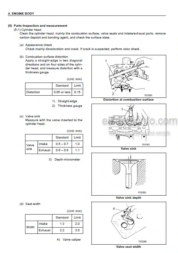
Cylinder Head Specifications
Camshaft And Timing Gear Train Specifications
Crankshaft And Piston Specifications
Cylinder Block Specifications
Special Torque Chart
Special Service Tools
Measuring Instruments
2-Valve Cylinder Head
4-Valve Cylinder Head
Measuring And Adjusting Valve Clearance
Crankshaft And Camshaft Components
EGR System
Before You Begin Servicing
Introduction
Fuel System Specifications
Special Service Tools
Measuring Instruments
Fuel System Diagram
Fuel System Components
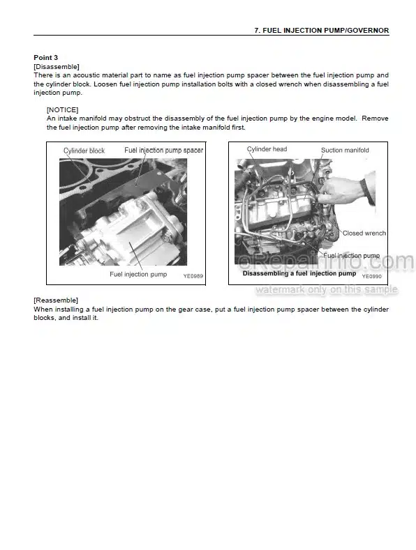
Fuel Injection Pump
Checking And Adjusting Fuel Injection Timing
Fuel Injectors
Before You Begin Servicing
Introduction
Cooling System Diagram
Engine Coolant Pump Components
Engine Coolant System Check
Engine Coolant Pump
Before You Begin Servicing
Introduction
Oil Pump Service Information
Lubrication System Diagram
Checking Engine Oil Pressure
Trochoid Oil Pump
Before You Begin Servicing
Introduction
Specifications
Troubleshooting
Turbocharger Components
Turbocharger Component Functions
Washing Procedure
Periodic Inspection
Before You Begin Servicing
Introduction
Starter Motor Information
Starter Motor Specifications
Starter Motor Troubleshooting
Starter Motor Components
Starter Motor
Before You Begin Servicing
Introduction
Dynamo And Alternator Information
Alternator Specifications
Dynamo Specifications
Alternator Troubleshooting
Alternator Components
Alternator Wiring Diagram
Alternator Standard Output
Alternator
Dynamo Component Location
Dynamo Wiring Diagram
Operation Of Dynamo
Dynamo Standard Output
Testing Of Dynamo
Dynamo
-TROUBLESHOOTING OF MECHANICAL SYSTEM
Special Service Tools
Troubleshooting By Measuring Compression Pressure
Quick Reference Table For Troubleshooting
What you get
You will receive PDF file with high-quality manual on your email immediately after the payment.


Reviews
There are no reviews yet.