


Factory Shop Manual For Komatsu Wheel Loader. Manual Contains Illustrations, Instructions, Diagrams For Step By Step Remove And Install, Assembly And Disassembly, Service, Inspection, Repair, Troubleshooting, Tune-Ups.
Format: PDF
Language: English
Pages: 1224
Number: SEBM013409 (april 2004)
Bookmarks: Yes
Searchable: Yes
Wiring Diagrams: Yes
Hydraulic Diagrams: Yes
Model
Komatsu Avance Wheel Laoder
WA800-3
Serial No. 50001 And Up
Contents
-FORWARD
Safety
Forward
Hoisting Instructions
Method Of Disassembling, Connecting Push-Pull Type Coupler
Coating Materials
Standard Tightening Torque
Electric Wire Code
Conversion Table
Units
-GENERAL
General Assembly Drawing
Specifications
Weight Table
List Of Lubricant And Water
-STRUCTURE AND FUNCTION
Power Train
Power Train System
Engine Control
Servo Cylinder
Radiator And Cooler
Damper
Torque Converter And Transmission Piping
Transmission Hydraulic System Diagram
Transmission Hydraulic Circuit Diagram
Torque Converter
Transmission
Transfer
Transmission Control Valve
Torque Converter Oil Cooler
Drive Shaft
Center Support
Axle
Final Drive
Axle Mount
Center Hinge Pin
Tire And Wheel
Steering Piping Diagram
Steering Column
Joystick Linkage
Steering Pump
Switch Pump
Steering Demand Valve
Steering Unit (Orbit-Roll Valve)
Proportional Solenoid Valve
EPC Valve
Rotary Valve
Two-Way Restrictor Valve
Diverter Valve
Brake Piping
Brake Circuit Diagram
Brake Valve
Charge Valve
Accumulator (For Brake)
Slack Adjuster
Brake
Parking Brake
Spring Cylinder
Parking Brake Solenoid Valve
Hydraulic Piping
Hydraulic Circuit Diagram
Work Equipment Lever Linkage
Hydraulic Tank
Main Piston Pump
ES Valve
Servo Valve
PPC Valve
PPC Relief Valve
Accumulator (For PPC Valve)
Work Equipment Control Lever
Work Equipment EPC Valve
Work Equipment Neutral Lock Solenoid Valve
Main Control Valve
Lubrication Of Work Equipment
Work Equipment Linkage
Bucket Positioner And Boom Kick-Out
Operation Of Proximity Switch
Cab
ROPS Canopy
Air Conditioner
Electric Circuit Diagram
Machine Monitor System
Main Monitor
Maintenance Monitor
Multi Monitor System (If Equipped)
Work Equipment Control System
Work Equipment Controller
Engine Starting Circuit
Engine Stop Circuit
Preheating Circuit
Electrical Transmission Control
Kick-Down, Hold Switch
Joystick Steering System
AJSS (Advanced Joystick Steering System)
Electric Parking Brake Control
-TESTING AND ADJUSTING
Standard Value Table
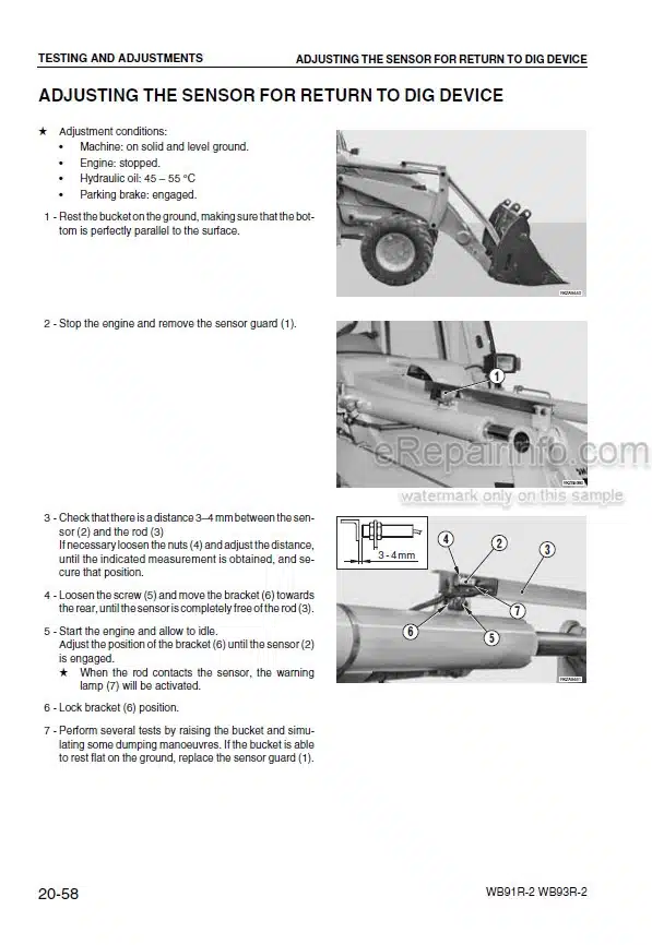
Testing And Adjusting
Troubleshooting
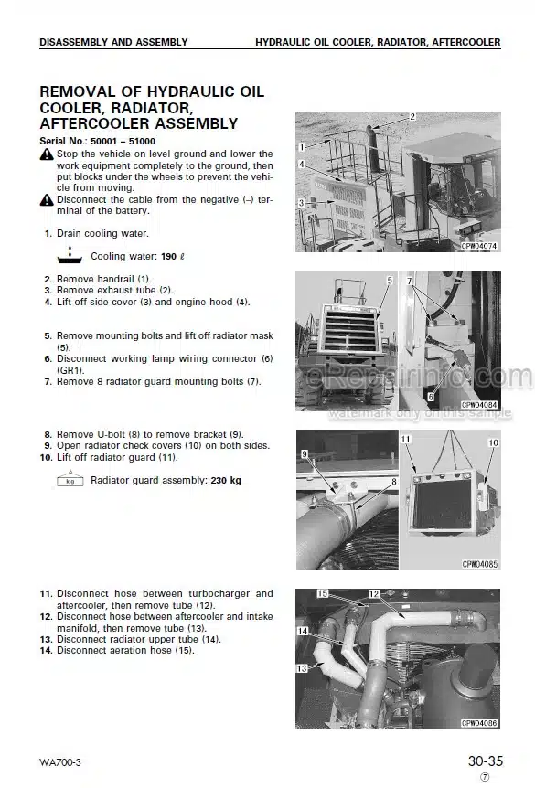
-DISASSEMBLY AND ASSEMBLY
Method Of Using Manual
Precautions When Carrying Out Operation
Special Tool List
Sketches Of Special Tools
Starting Motor – Removal And Installation
Alternator – Removal And Installation
Engine Oil Cooler – Removal And Installation
Fuel Injection Pump For Left Bank – Removal And Installation (With Governor)
Fuel Injection Pump For Right Bank – Removal And Installation (Without Governor)
Water Pump – Removal And Installation
Nozzle Holder – Removal And Installation
Turbocharger – Removal And Installation
Engine Front Seal – Removal And Installation
Engine Rear Seal – Removal And Installation
Cylinder Head
Radiator
Engine
Damper
Torque Converter And Transmission Assembly
Torque Converter
Torque Converter Valve – Disassembly And Assembly
Transmission
Transmission Valve
Transfer
PTO
Center Support
Drive Shaft
Front Axle
Rear Axle
Differential
Final Drive
Orbit-Roll
Emergency Steering Pump – Removal And Installation
Diverter Valve
Accumulator Charge Valve
Steering Stop Valve
Steering Cylinder
Steering Valve
Brake Valve – Removal And Installation
Slack Adjuster
Brake
Parking Brake Calipers
Parking Brake Pad – Removal And Installation
Parking Brake Spring Cylinder – Removal And Installation
Brake Oil Tank – Removal And Installation
Hydraulic Pump
Piston Pump Disassembly
Servo Cylinder – Removal And Installation
Hydraulic Tank And Filter Case Assembly
PPC Valve
Work Equipment Control Valve
Cab
Floor Frame
Center Hinge Pin
Work Equipment
Boom Front End Bush – Replacement
Bucket Cylinder – Removal And Installation
Lift Cylinder
Hydraulic Cylinder
Air Conditioner Unit
Air Conditioner Compressor
Receiver Tank – Removal And Installation
Air Conditioner Condenser – Removal And Installation
Transmission And Steering Controller – Removal And Installation
Main Monitor
Fuel Tank
Counterweight – Removal And Installation
-MAINTENANCE STANDARD
Engine Mount
Transmission Mount
Damper
Torque Converter Charging, Ppc And Brake Pump
Torque Converter
Torque Converter Regulator Valve
Transmission
Transfer
Transmission Control Valve
Drive Shaft
Center Support
Differential
Final Drive
Axle Mount
Center Hinge Pin
Steering Column
Steering Demand Valve
Diverter Valve
Steering Cylinder Mount
Emergency Steering Pump
Brake Valve
Slack Adjuster
Brake
Parking Brake
PPC Valve
PPC Relief Valve
Control Pump
Steering Pump
Switch Pump
Main Piston Pump
Main Control Valve
Hydraulic Cylinder
Bucket Linkage
Bucket Positioner And Boom Kick-Out
-OTHERS
Electric Circuit Diagram
What you get
You will receive PDF file with high-quality manual on your email immediately after the payment.


Reviews
There are no reviews yet.