


Factory Shop Manual For Komatsu Super Dozer. Manual Contains Illustrations, Instructions, Diagrams For Step By Step Remove And Install, Assembly And Disassembly, Service, Inspection, Repair, Troubleshooting, Tune-Ups.
Format: PDF
Language: English
Pages: 866
Number: SEBM022003 (may 2008)
Bookmarks: Yes
Searchable: Yes
Wiring Diagrams: Yes
Hydraulic Diagrams: Yes
Model
Komatsu Super Dozer
D575A-3
SN 10101 And Up
Contents
-SAFETY
Safety Notice
-FOREWORD
General
How To Read The Shop Manual
Hoisting Instructions
Method Of Disassembling, Connecting Push-Pulltype Coupler
Coating Materials
Standard Tightening Torque
Electric Wire Code
Conversion Table
Units
-GENERAL
Specification Drawing
Specifications
Weight Table
Table Of Fuel, Coolant And Lubricants
-STRUCTURE AND FUNCTION, MAINTENANCE STANDARD
Radiator, Oil Cooler
Engine Control
Powertrain System
Powertrain Section
Powertrain Hydraulic Piping
Damper
Torque Converter, PTO
Torque Converter Valve
Torque Converter Lock-Up Control System
Torque Converter Filter
Transmission Control
Transmission
Transmission Control Valve
Lubrication Relief Valve
Steering Clutch, Brake Control
Steering Control Valve
Steering Clutch, Steering Brake
Final Drive
Track Frame
Idler
Carrier Roller
Track Roller
Track Shoe
Recoil Spring
Track Roller Bogie
Suspension
Hydraulic Piping Diagram For Work Equipment
Centralized Oil Pressure Detection Piping Diagram
Hydraulic Tank
Pitch. Tilt Selector Solenoid Valve Assembly
PPC Valve
Safety Lock Valve, PPC Accumulator
PPC Relief Valve
Main Control Valve
Pitch Selector Solenoid Valve
Pitch Priority Solenoid Valve
Pitch Assist Solenoid Valve
Blade Control Knob
Piston Valve
Quick Drop Valve
Work Equipment Cylinder
Cylinder Stay, Yoke
Work Equipment
Counterweight
Air Conditioner
Engine Control System
Engine Control System With Electronic Engine Throttle Controller
Monitor System
Sensor
Mode Selection System
Blade Control System
Actual Electrical Wiring Diagram
-TESTING AND ADJUSTING
Standard Value Table For Engine
Standard Value Table For Chassis
Standard Value Table For Electrical Related Parts
Testing And Adjusting
Troubleshooting
-DISASSEMBLY AND ASSEMBLY
Precautions When Carrying Out Operation
Special Tool List
Engine Oil Cooler
Fuel Injection Pump
After-Cooler Core
Nozzler Holder
Cylinder Head
Hydraulic Cooler
Radiator
Fan Drive Support
Fan Drive Pulley (Fan End)
Fan Drive Pulley (Engine End)
Damper
Powertrain
PTO, Torque Converter
PTO
Torque Converter
Torqflow Transmission
Steering Case
Steering Clutch
Steering Brake
Torque Converter Valve
Transmission Control Valve
Powertrain Pump
Transmission Lubrication Pump
Scavenging Pump
Final Drive
Track Frame
Recoil Spring, Tube
Idler Yoke Cylinder
Idler
Track Roller
Bogie
Track Shoe
Press-Fitting Jig Dimension Table For Link Press
Field Disassembly Of One Link
Master Link
Adjusting Track Shoe Tension
Pivot Shaft
Equalizer Bar
Replacing Equalizer Bar Bushing
Segment Teeth
Work Equipment Pump
Work Equipment Assist, Control Pump
Blade Valve
Main Relief Valve
Blade Lift Cylinder
Blade Pitch Cylinder
Hydraulic Cylinder
Blade PPC Value
Blade
Potentiometer
Operator’s Compartment Frame
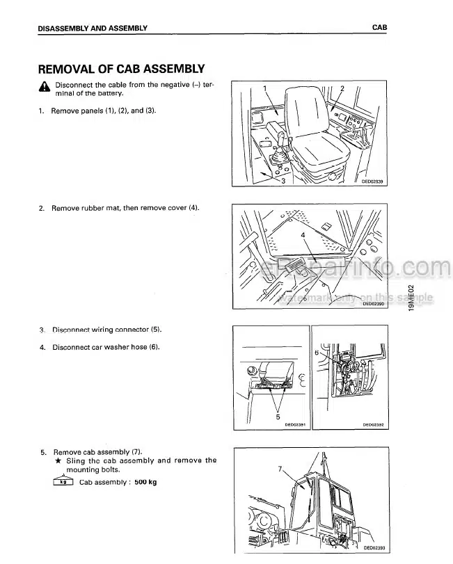
Cab
ROPS
Counterweight Frame
Blade Cylinder Support
-OTHERS
Power Train Hydraulic Circuit Diagram
Hydraulic Circuit Diagram For Work Equipment
Electrical Circuit Diagram
What you get
You will receive PDF file with high-quality manual on your email immediately after the payment.


Reviews
There are no reviews yet.