Factory Field Assembly Instructions For Komatsu Wheel Loader.
Format: PDF
Language: English
Pages: 145
Number: GEN00056-06 (july 2011)
Bookmarks: Yes
Searchable: Yes
Model
Komatsu Wheel Loader
WA800-3E0
SN 70001 And Up
WA900-3E0
SN 60001 And Up
Contents
DIVIDING PROCESS OVERVIEW (MAJOR COMPONENTS ALONE)
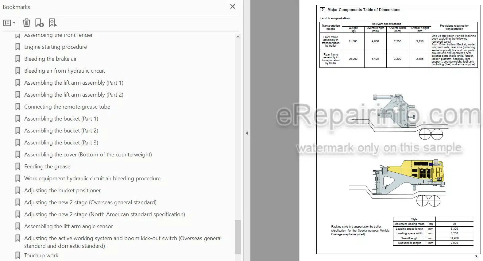
MAJOR COMPONENTS TABLE OF DIMENSIONS
WORK SPACE LAYOUT
SCHEDULE TABLE FOR FIELD ASSEMBLY
FACILITY, JIGS AND TOOLS
-LIST OF OIL, GREASE AND PAINTS
Oil, Grease And Coolant
Oil, Grease And Coolant Level
Setting Rear Frame In Place
Setting Front Frame In Place
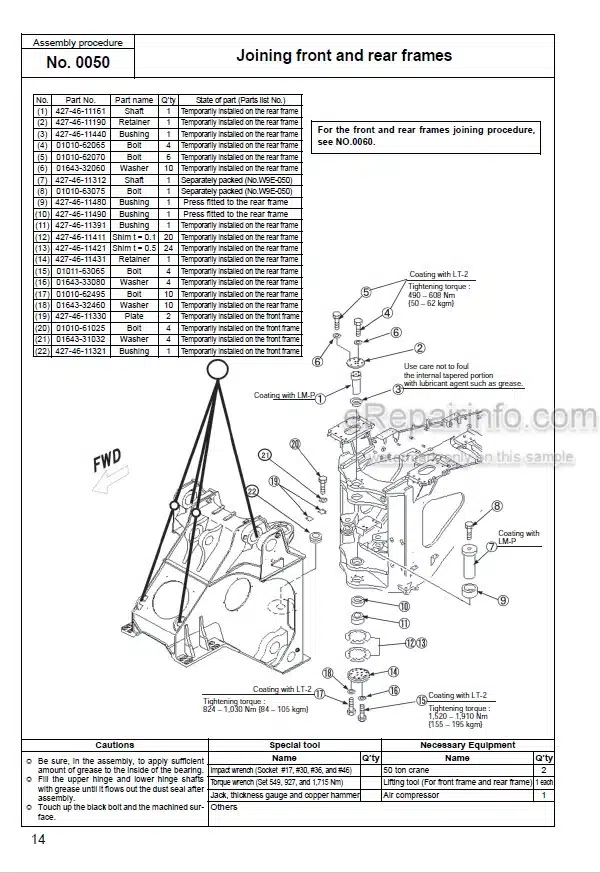
Joining Front And Rear Frames
Front And Rear Frames Joining Procedure
Assembling The Steering Pin
Assembling The Center Drive Shat (Center Support • Transmission)
Connecting The Pipes – Part 1
Connecting The Pipe – Part 2
Connection Of Piping (Part 2) (7Xc47: Front And Rear Frame Combination Load Figure)
Connection Of Piping (Part 2) (Riotinto Specification: If Equipped)
Connecting The Auto-Greasing Pipe
Setting The Axle In Place And Assembling The Support
Setting The Bare Machine In Place
Assembling The Rear Axle
Rear Axle Rear Side Cover Assembling Procedure
Connecting The Rear Axle Pipe
Fixing Of Rear Axle Piping (Brake Cooling Specification: If Equipped)
Connection Of Rear Axle Piping (Riotinto Specification: If Equipped)
Fixing Of Rear Axle Piping (Brake Cooling Specification: If Equipped)
Connection Of Cooling Line Piping (Brake Cooling Specification: If Equipped)
Assembling The Rear Drive Shat (Transmission – Rear Axle)
Assembling The Front Axle
Fixing Of Front Axle Piping (Brake Cooling Specification: If Equipped)
Connection Of Front Axle Piping (Brake Cooling Specification: If Equipped)
Connecting The Front Axle Pipe
Connection Of Front Axle Piping (Riotinto Specification: If Equipped)
Connecting The Front Drive Shat (Front Axle • Center Support)
Connection Of Front Axle Brake Oil Temperature Sensor
Connecting The Axle Oil Temperature Sensor (For VHMS Specification Only)
Assembling The Tires
Assembling The Fuel Tank
Installation Of Fuel Tank (Riotinto Specification: If Equipped)
Fixing The Drain Pipe
Fixing Of Torque Converter Cooler Drain Piping (Riotinto Specification: If Equipped)
Connecting The Fuel Pipe
Fixing Of Breather Hose
Fixing The Engine Drain Hoses
Assembling The Hydraulic Tank Ladder
Assembling The Floor And Cab Assembly
Connecting The Air Conditioner Hose
Connecting The Brake Line
Connecting The Window Washer Hose
Connecting The PPC Line Hose
Connecting The Floor Wiring Harness
Connecting The Floor Wiring Harness (Steering Wheel Specification: If Equipped)
Connection Of Floor Wiring Harness -1 (Riotinto Specification: If Equipped)
Connection Of Floor Wiring Harness -2 (Riotinto Specification: If Equipped)
Connecting The Steering Line (Steering Wheel Specification: If Equipped)
Connecting The Link For AJSS (For AJSS Specification Only)
Calibration Of The AJSS Angle And Frame Offset Angle
Assembling The Auto-Greasing Pump And Connecting The Pipe (Wa900-3E0 North American Specification)
Assembling The Floor Cover
Refilling The Window Washer
Assembling The Battery Box
Connecting And Fixing The Battery Wiring
Wiring On Right Side Of Battery (Riotinto Specification: If Equipped)
Wiring On Left Side Of Battery -1 (Riotinto Specification: If Equipped)
Wiring On Left Side Of Battery -2 (Riotinto Specification: If Equipped)
Wiring On Left Side Of Battery -3 (Riotinto Specification: If Equipped)
Connection Of Ground Cable On Left Side Of Battery (Riotinto Specification: If Equipped)
Assembling The Battery Step
Installation Of Oil Cooler Assembly (Brake Cooling Specification: If Equipped)
Installation And Connection Of Oil Cooler Assembly Piping (Brake Cooling Specification: If Equipped)
Installation Of Oil Cooler Assembly Piping -1 (Brake Cooling Specification: If Equipped)
Installation Of Oil Cooler Assembly Piping -2 (Brake Cooling Specification: If Equipped)
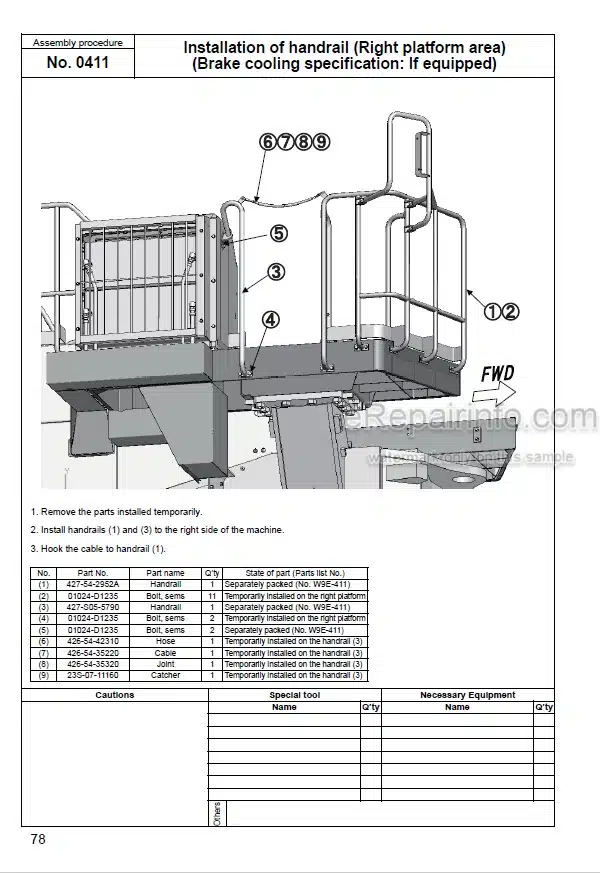
Assembling The Handrail (On The Right Hand Platform)
Installation Of Handrail (Right Platform Area) (Brake Cooling Specification: If Equipped)
Assembling The Handrail (On The Hood Top Face)
Assembling The Handrail (On The Right Hand Battery Box)
Assembling The Rear Access Step
Assembling The Left Handrail (Part 2)
Installation Of Left Handrail (Part 2) (Brake Cooling Specification: If Equipped)
Assembling The Rearview Mirror
Installation Of Rearview Mirrors (Brake Cooling Specification: If Equipped)
Assembling The Exhaust Pipe
Installation Of Oil Cooler Guard Assembly (Brake Cooling Specification: If Equipped)
Installation Of Fan Motor Piping Cover -1 (Brake Cooling Specification: If Equipped)
Installation Of Fan Motor Piping Cover -2 (Brake Cooling Specification: If Equipped)
Applying The Counterweight Anti-Slip
Assembling The Counterweight (WA900-3E0 Standard Specification)
Assembling The Counterweight (WA900-3E0 High-Lift Arm Specification)
Assembling The Counterweight(WA800-3E0 Overseas General, Optional Specification And North American Specification)
Assembling The Counterweight (WA800-3E0 Overseas General Standard Specification)
Assembling The Front Axle Lamp And Connecting The Harness
Assembling The Front Lamp Assembly
Assembling The ROPS Canopy Assembly
Assembling The Antenna And Work Lamp
Assembling The VHMS Antenna (For VHMS Specification Only)
Assembling The Floor Mat
Assembling The Front Fender
Engine Starting Procedure
Bleeding The Brake Air
Bleeding Air From Hydraulic Circuit
Assembling The Lift Arm Assembly
Connecting The Remote Grease Tube
Assembling The Bucket
Assembling The Cover (Bottom Of The Counterweight)
Feeding The Grease
Work Equipment Hydraulic Circuit Air Bleeding Procedure
Adjusting The Bucket Positioner
Adjusting The New 2 Stage (Overseas General Standard)
Adjusting The New 2 Stage (North American Standard Specification)
Assembling The Lift Arm Angle Sensor
Adjusting The Active Working System And Boom Kick-Out Switch (Overseas General Standard And Domestic Standard)
Touchup Work
Applying The Decal (For The Overseas-Directed Products Only)
APPENDIX: FIELD ASSEMBLY INSPECTION REPORT
What you get
You will receive PDF file with high-quality manual on your email immediately after the payment.
Reviews
There are no reviews yet.