


Factory Shop Manual For Komatsu Motor Grader. Manual Contains Illustrations, Instructions, Diagrams For Step By Step Remove And Install, Assembly And Disassembly, Service, Inspection, Repair, Troubleshooting, Tune-Ups.
Format: PDF
Language: English
Pages: 713
Number: SEBM020908 (march 2006)
Bookmarks: Yes
Searchable: Yes
Wiring Diagrams: Yes
Hydraulic Diagrams: Yes
Model
Komatsu Motor Grader
GD555-3C
SN 50001 And Up
GD655-3C
SN 50001 And Up
GD675-3C
SN 50001 And Up
Contents
FOREWORD
-GENERAL
General Assembly Drawing
Specifications
Weight Table
Fuel, Coolant And Lubricant Selection
-STRUCTURE, FUNCTION AND MAINTENANCE STANDARD
Accelerator Control Linkage
Accelerator Pedal
Fan Drive
Powertrain Diagram
Transmission Hydraulic Piping
Transmission Control
Torque Converter
Torque Converter Lock-Up Valve (ECMV)
Transmission
Transmission Valve
ECMV (Electronic Control Modulation Valve)
Main Relief Valve
Transmission Pump
Transmission And Differential Lock Pump (With Differential Lock)
Final Drive
Tandem Drive
Steering Hydraulic Piping Drawing
Steering Valve (Q/Amp Manual Orbit-Roll Type)
Priority ACC Governor Valve (Serial No.50001-51000)
Priority Valve (Serial N0.51001 And Up)
Accumulator Pressure Governor Valve (Serial N0.51001 And Up)
Front Axle
Brake Hydraulic Piping
Brake Valve
Wheel Brake
Slack Adjuster
Accumulator
Parking Brake
Parking Brake And Bank Control Valve
Work Equipment Hydraulic Piping Drawing
Hydraulic Pump (Serial N0.50001-51000)
Hydraulic Pump (Serial N0.51001 And Up)
Main Control Valve
CLSS
Work Equipment Control
Hydraulic System
Hydraulic Tank
Swivel Joint
Pilot Check Valve
Blade Accumulator, Float Valve
Shut-Off Valve
Blade Float Device
Circle Rotation Motor
Hydraulic Cylinder
Circle, Drawbar
Lifter Bracket Lock Pin
Blade
Circle Rotation Gear
Scarifier
Ripper
Main Frame
Air Conditioner (If Equipped)
Engine Starting Circuit
Engine Stop Circuit
Preheat Circuit
Automatic Shift Control System
Transmission Controller
Monitor
Sensors
-TESTING AND ADJUSTING
Standard Value Table
Testing And Adjusting
Troubleshooting
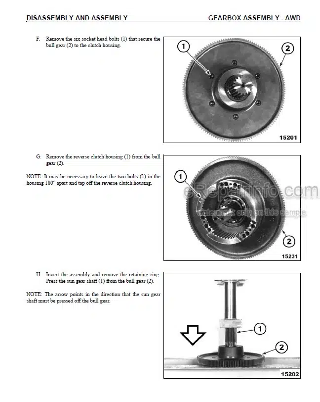
-DISASSEMBLY AND ASSEMBLY
Precautions When Carrying Out Operation
Special Tool List
Sketches Of Special Tools
Removal Of Engine Hood Assembly (Serial N0.:50001-51000)
Installation Of Engine Hood Assembly (Serial N0.:50001-51000)
Removal Of Engine Hood Assembly (Serial No.:51001 And Up)
Installation Of Engine Hood Assembly (Serial No.:5101 And Up)
Removal Of Radiator Assembly (Serial N0.:50001-51000)
Installation Of Radiator Assembly (Serial N0.:50001-51000)
Removal Of Radiator Assembly (Serial No.:51001 And Up)
Installation Of Radiator Assembly (Serial No.:51001 And Up)
Removal Of Fuel Tank, Hydraulic Tank, And Cooling Water Sub Tank Assembly (Serial N0.:50001-51000)
Installation Of Fuel Tank, Hydraulic Tank, And Cooling Water Sub Tank Assembly (Serial N0.:50001-51000)
Removal Of Fuel Tank. Hydraulic Tank. And Cooling Water Sub Tank Assmbly (Serial No.:51001 And Up)
Installation Of Fuel Tank, Hydraulic Tank, And Cooling Water Sub Tank Assembly (Serial No.:51001 And Up)
Removal Of Engine Assembly
Installation Of Engine Assembly
Removal Of Engine Assembly, Transmission Assembly As One Unit
Installation Of Engine Assembly, Transmission Assembly As One Unit
Removal Of Transmission Assembly
Installation Of Transmission Assembly
Disassembly Of Torque Converter Assembly
Assembly Of Torque Converter Assembly
Disassembly Of Transmission Assembly
Assembly Of Transmission Assembly
Removal Of Final Drive Assembly
Installation Of Final Drive Assembly
Disassembly Of Final Drive Assembly
Assembly Of Final Drive Assembly
Disassembly Of Final Brake Case
Assembly Of Final Brake Case
Disassembly Of Side Case
Assembly Of Side Case
Disassembly Of Differential Gear Assembly
Assembly Of Differential Gear Assembly
Disassembly Of Bevel Gear
Assembly Of Bevel Gear
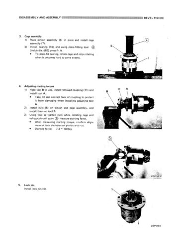
Disassembly Of Bevel Pinion Assembly
Assembly Of Bevel Pinion Assembly
Removal Of Operator’s Cab Assembly
Installation Of Operator’s Cab Assembly
Removal Of Operator’s Cab Floor
Installation Of Operator’s Cab Floor
Removal Of Steering Valve (Orbit-Roll)
Installation Of Steering Valve (Orbit-Roll)
Standard Integral Orbit-Roll
Disassembly Of Steering Valve
Assembly Of Steering Valve
Removal Of Blade Assembly
Installation Of Blade Assembly
Removal Of Circle Drawbar Assembly
Installation Of Circle Drawbar Assembly
Removal Of Blade Circle Gear Assembly
Installation Of Blade Circle Gear Assembly
Removal Of Blade Circle Rotation Gear Assembly (With Shear Pin)
Installation Of Blade Circle Rotation Gear Assembly (With Shear Pin)
Disassembly Of Blade Circle Rotation Gear Assembly (With Shear Pin)
Assembly Of Blade Circle Rotation Gear Assembly (With Shear Pin)
Disassembly Of Circle Rotating Gear Assembly (With Slip Clutch)
Assembly Of Circle Rotating Gear Assembly (With Slip Clutch)
-OTHERS
Transmission Hydraulic Circuit
Hydraulic Circuit Diagram
Electrical Circuit Diagram
What you get
You will receive PDF file with high-quality manual on your email immediately after the payment.


Reviews
There are no reviews yet.