


Factory Shop Manual For Komatsu Articulated Dump Truck. Manual Contains Illustrations, Instructions, Diagrams For Step By Step Remove And Install, Assembly And Disassembly, Service, Inspection, Repair, Troubleshooting, Tune-Ups.
Format: PDF
Language: English
Pages: 1112
Number: SEBM023017 (august 2012)
Bookmarks: Yes
Searchable: Yes
Wiring Diagrams: Yes
Hydraulic Diagrams: Yes
Model
Komatsu Articulated Dump Truck
HM400-1
SN 1001 And Up
Contents
-GENERAL
Specification Drawings
Specifications
Weight Table
Fuel, Coolant And Lubricants
-STRUCTURE,FUNCTION AND MAINTENANCE STANDARD
Radiator, Oil Cooler, Aftercooler
Powertrain Skeleton
Output Shaft
Torque Converter And Transmission Hydraulic Piping
Torque Converter
Transmission
Transmission Valve
ECMV (Electronic Control Modulation Valve)
Main Relief, Torque Converter Relief Valve
Drive Shaft
Axle
Differential
Limited Slip Differential
Final Drive
Steering Column
Brake Piping
Brake Valve
Accumulator Charge Valve
Accumulator
Slack Adjuster
Brake
Proportional Reducing Valve
Brake System Tank
Parking Brake
Parking Brake Caliper
Spring Cylinder
Parking Brake Solenoid
Suspension
Suspension Cylinder
Oscillation Hitch
Steering, Hoist Oil Pressure Piping Diagram
Dump Body Control
Hydraulic Tank And Filter
Flow Amp Valve
Steering Valve
Steering Cylinder
Hoist Valve
EPC Valve
Pilot Check Valve
Hoist Cylinder
Hydraulic Pump
Cab Tilt
Air Conditioner
Machine Monitor System
Automatic Shift Control System
Transmission Controller
Auto Emergency Steering System
Sensors, Switches
Retarder Control System
Brake Control System (E-Spec)
Dump Control Lever
PLM-HM
-TESTING AND ADJUSTING
Standard Value Table For Engine
Standard Value Table For Chassis
Standard Value Table For Electrical Parts
Testing And Adjusting
Troubleshooting
-DISASSEMBLY AND ASSEMBLY
Precautions When Carrying Out Operation
Special Tool List
Sketches Of Special Tools
Removal Of Fuel Supply Pump
Installation Of Fuel Supply Pump
Removal Of Engine Assembly
Installation Of Engine Assembly
Removal Of Cylinder Head Assembly
Installation Of Cylinder Head
Removal And Installation Of Nozzle Tip
Removal Of Radiator Assembly
Installation Of Radiator Assembly
Removal Of Output Shaft Assembly
Installation Of Output Shaft Assembly
Disassembly Of Output Shaft Assembly
Assembly Of Output Shaft Assembly
Removal Of Transmission And Front Differential Assembly
Installation Of Transmission And Front Differential Assembly
Disconnection Of Front Differential And Transmission
Coupling Of Front Differential And Transmission
Disassembly Of Torque Converter Assembly
Assembly Of Torque Converter Assembly
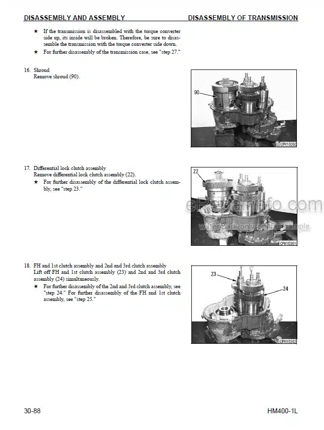
Disassembly Of Transmission Assembly
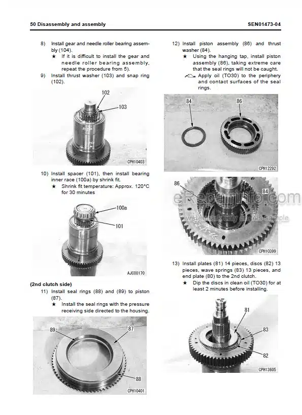
Assembly Of Transmission Assembly
Disassembly Of Front Differential Assembly
Assembly Of Front Differential Assembly
Removal Of Center Differential Assembly
Installation Of Center Differential Assembly
Disassembly Of Center Differential Assembly
Assembly Of Center Differential Assembly
Removal Of Rear Differential Assembly
Installation Of Rear Differential Assembly
Disassembly Of Rear Differential Assembly
Assembly Of Rear Differential Assembly
Removal Of Front Final Drive And Brake Assembly
Installation Of Front Final Drive And Brake Assembly
Disassembly Of Front Final Drive And Brake Assembly
Assembly Of Front Final Drive And Brake Assembly
Removal Of Center Final Drive And Brake Assembly
Installation Of Center Final Drive And Brake Assembly
Disassembly Of Center Final Drive And Plate Assembly
Assembly Of Center Final Drive And Brake Assembly
Removal Of Rear Final Drive And Brake Assembly
Installation Of Rear Final Drive And Brake Assembly
Disassembly Of Rear Final Drive And Brake Assembly
Assembly Of Rear Final Drive And Brake Assembly
Removal Of Center Axle Assembly
Installation Of Center Axle Assembly
Removal Of Rear Axle Assembly
Installation Of Rear Axle Assembly
Removal Of Front Suspension Cylinder Assembly
Installation Of Front Suspension Cylinder Assembly
Removal Of Rear Suspension Cylinder Assembly
Installation Of Rear Suspension Cylinder Assembly
Disassemble And Assembly Of Front And Rear Suspension Cylinder Assembly
Removal Of Equalizer Bar Assembly
Installation Of Equalizer Bar Assembly
Removal Of Front Wheel Assembly
Installation Of Front Wheel Assembly
Removal, Installation Of Rear Wheel Assembly
Removal Of Hitch Frame Assembly
Installation Of Hitch Frame Assembly
Disassembly Of Hitch Frame
Assembly Of Hitch Frame Assembly
Standard Integral Orbit-Roll
Disassembly Of Steering Valve
Assembly Of Steering Valve
Removal Of Flow Amplifier Valve Assembly
Installation Of Flow Amplifier Valve Assembly
Removal Of Hoist Valve Assembly
Installation Of Hoist Valve Assembly
Assembly Of Hoist Valve Assembly
Disassembly Of Steering Cylinder Assembly
Assembly Of Steering Cylinder Assembly
Disassembly Of Hoist Cylinder Assembly
Assembly Of Hoist Cylinder Assembly
Removal Of Body Assembly
Installation Of Body Assembly
Disassembly And Assembly Of Operator’s Seat Assembly
-OTHERS
Power Train Hydraulic Circuit Diagram
Steering And Hoist Hydraulic Circuit Diagram
Differential Lock Hydraulic Circuit Diagram
Brake Hydraulic Circuit Diagram
Brake Cooling Hydraulic Circuit Diagram
Diagram For Electrical Circuit Air Conditioner
Diagram For Electrical Circuit Inside Cab
Diagram For Electrical Circuit Outside Cab
Payload Meter Electrical Circuit
What you get
You will receive PDF file with high-quality manual on your email immediately after the payment.


Reviews
There are no reviews yet.