


Factory Shop Manual For Komatsu Diesel Engine. Manual Contains Illustrations, Instructions, Diagrams For Step By Step Remove And Install, Assembly And Disassembly, Service, Inspection, Repair, Troubleshooting, Tune-Ups.
Format: PDF
Language: English
Quantity of manuals: 3
Pages: 404; 64; 652
Number: unknown; CEBM610AR0; CEBM610TR0
Bookmarks: Yes
Searchable: Yes
Model
Komatsu Engine
KDC410
KDC610
Contents
-INTRODUCTION
About the Manual
General Cleaning Instructions
General Repair Instructions
General Safety Instructions
Generic Symbols
Glossary of Terms
How to Use the Manual
Illustrations
-ENGINE AND COMPONENT IDENTIFICATION
Engine Diagram
Engine Identification
Injection Pump Dataplate
-TROUBLESHOOTING
Troubleshooting Symptoms Charts
-COOLING SYSTEM
Belt Tensioner – Replacement
Coolant
Coolant System Components and Flow
Coolant System Malfunctions
Cooling System Specifications
Cup Plugs – Replacement
Drive Belt – Replacement
Fan Hub – Replacement
Fan Pulley – Replacement
Thermostat – Replacement
Water Pump – Replacement
-LUBRICATING OIL SYSTEM
Cup Plugs – Replacement
Diagnosing Lubricating System Malfunctions
Flow Diagrams – Lubricating System
General Information – Lubrication System
High Oil Pressure
Low Oil Pressure
Lubrication for the Power Components
Lubrication for the Turbocharger
Oil Cooler Element and/or Gasket – Replacement
Oil Leaks
Oil Pan, Suction Tube and/or Gaskets – Replacement
Oil Pressure Regulating Valve
Oil Pressure Regulator Valve/ Spring – Replacement
Oil Pump – Replacement
Specifications – Lubricating Oil System
-COMBUSTION AIR SYSTEM
Aftercooler and Gasket
Air Crossover Tube
Air System Flow – Diagrams
Combustion Air System Flow – General Information
Combustion Air System – Service Tools
Diagnosing Air System Malfunctions
Exhaust Manifold and Gaskets
Intake Air and Exhaust System Specifications
Intake Manifold Cover and Gasket
Turbocharger
Turbocharger Boost Pressure Specifications
Turbocharger – Testing
-COMPRESSED AIR SYSTEM
Air Compressor – Removal
Air Governor and Compressor Unloader Valve – Check
Air Governor – Check
Carbon Buildup, Air Compressor – Check
Compressed Air System – General Information
Compressed Air System – Service Tools
Flow Diagrams – Compressed Air System
Gasket Leaks, Air Compressor, Check
Specifications – Compressor Air System
Unloader and Cylinder Head Disassembly
-FUEL SYSTEMS
Air Fuel Control Tube Replacement – Bosch VE Pump
Air In The Fuel System
Back Leakage Valve and Sealing Washer (Lucas CAV DPA) – Replacement Delivery Valve Holder and Sealing Washer (Bosch VE) – Replacement External Pump Leaks – Repair
Fuel Drain Manifold
Fuel Drain Manifold Replacement
Fuel Filter – Replacement
Fuel Shut Off Valve Replacement – Bosch VE
Fuel System Components and Flow
Fuel System Identification
Fuel System – Service Tools
Fuel System Specifications
Fuel Transfer (Lift) Pump Diagnosing Malfunctions
Fuel Transfer (Lift) Pump – Testing
Fuel Water Separator/Filter Unit
General Information – Fuel Systems
High Pressure Fuel Lines
High Pressure Line Replacement
Idle Speed Adjustment
Injection Pump Replacement (Bosch VE and Lucas CAV DPA)
Injection Pump Supply Line Replacement
Injection Pump Timing
Injection Pump – Troubleshooting
Injector – Replacement
Injectors
Low Pressure Fuel Line Replacement
Pump Timing Check – (Lucas CAV DPA)
Timing Check – (Bosch VE Pump)
Transfer (Lift) Pump Replacement
Venting the Fuel Systems
-ELECTRICAL SYSTEM
Alternator – Checking
Alternator – Replacement
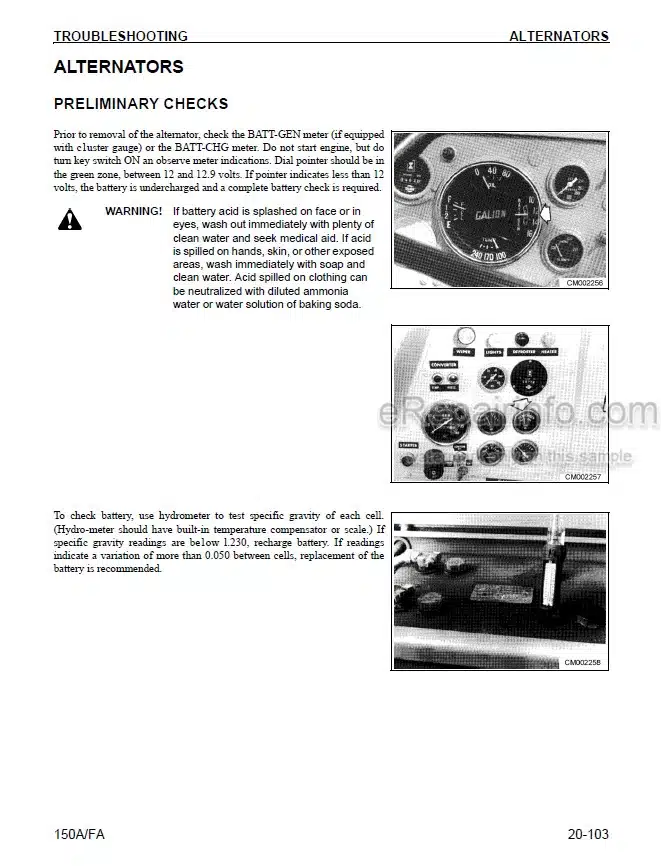
Battery Checking
Battery Terminal Connections – Checking
Block Water Heater Replacement
Coolant or Pan Heater – Check
Electrical System – Service Tools
Engine Electrical System Replacement Procedures
Flow Diagrams – Electrical System
General Information – Electrical System
Oil Pan Heater Replacement
Oil Pressure Switch and Temperature Sensor – Checking
Oil Pressure Switch – Replacement
Starting Circuit – Checking
Starting Motor – Replacement
Temperature Sensor – Replacement
-BASE ENGINE COMPONENTS SYSTEM
Base Engine Components – General Information
Base Engine Components – Replacement Procedures
Base Engine Components Specifications
Camshaft and Tappet – Replacement
Camshaft Gear – Replacement
Connecting Rod Bearing – Replacement
Connecting Rods – Replacement
Crankshaft Gear – Replacement
Cup Plug Replacement
Cylinder Bore Deglaze
Cylinder Head – Replacement
Diagnosing Base Engine Component Malfunctions
Exhaust Manifold – Replacement
Flywheel Housing – Replacement
Flywheel/Ring Gear – Replacement
Front Seal – Replacement
Gear Cover – Replacement
Gear Housing or Gasket – Replacement
Main Bearing – Replacement
Operation and Description Cylinder Head and Valve Train
Pipe Plug – Replacement
Piston and Rings – Replacement
Rear Seal – Replacement
Timing Pin Assembly – Replacement
Turbocharger – Replacement
Valves – Adjustment
Vibration Damper/Crank Pulley – Replacement
-ENGINE TESTING
Blowby Conversion Chart (5.613 mm [0.221 in] Orifice)
Engine Run-In Procedure
Engine Testing – Engine Side Views
Engine Testing – General Information
Engine Testing – Service Tools
General Engine Test Procedures
-ENGINE REMOVAL AND INSTALLATION
-ENGINE COMPONENT SPECIFICATIONS
Capscrew Markings and Torque Values
Component Specifications and Torque Values
Drive Belt Tension
Newton-Meter to Foot-Pound Conversion Chart
Pipe Plug Torque Values
Tap-Drill – U.S. Customary & Metric
Weight and Measures – Conversion F actors
-SERVICE LITERATURE
What you get
You will receive PDF file with high-quality manual on your email immediately after the payment.


Reviews
There are no reviews yet.