


Factory Service Manual And Assembly Procedure For Komatsu Hydraulic Excavator. Manual Contains Illustrations, Instructions, Diagrams For Step By Step Remove And Install, Assembly And Disassembly, Service, Inspection, Repair, Troubleshooting, Tune-Ups.
Format: PDF
Language: English
Pages: 594
Issued: december 2005
Bookmarks: Yes
Searchable: Yes
Model
Komatsu Hydraulic Excavator
PC3000-1 Electro
Contents
-GENERAL ASSEMBLY PROCEDURES
General
Assembly Sequence
SAFETY – FOREWORD
TECHNICAL DATA (LEAFLET)
ASSEMBLY PROCEDURE (BROCHURE)
-MAIN ASSEMBLY GROUPS
General Layout
Drive
Control Blocks, Swing Gear
Under Carriage, Travel Drive
Driver’s Cab
-DRIVE
Prime Drive Assembly
Engine Mounts
Fan Drive Assy
Coupling
Air Cleaner
Pump Distributor Gearbox
Pump Spline Lubrication
PTO- Gear Lubrication
Hydraulic Pump Location
-HYDRAULIC OIL TANK
Main Hydraulic Tank
Return And Leak Oil Filter
Breather Filter
Location Of Pressure Switches And Sensors
-HYDRAULIC OIL COOLING
General
Cooling Circuit
Adjustments
Fan Drive
Pressure Relief Valve And Solenoid Valve
Axial Piston Pump
Adjustments
Function Check Of Fan Speed Control
-CONTROLLING
Pilot Pressure Supply
Checks And Adjustments Of Pilot Pressure
Checking The Accumulator Function
Travel Parking Brake
Function Check Of Travel Parking Brake
Swing Parking (House) Brake
-COMPONENTS
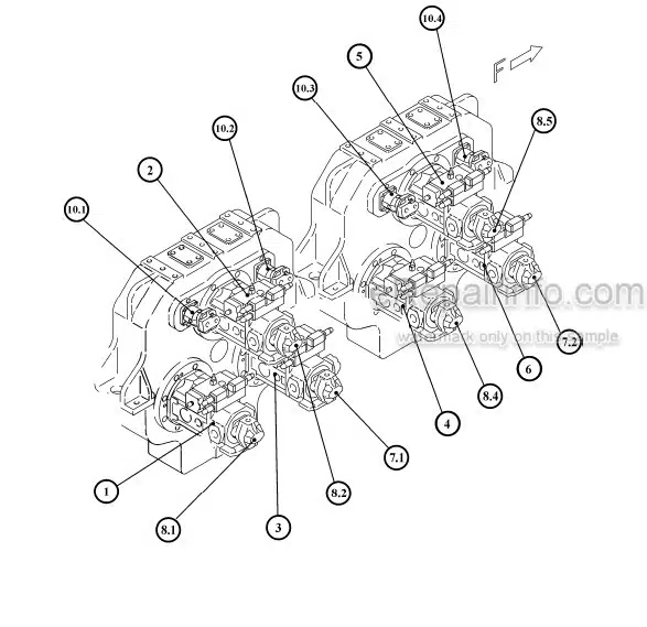
Main Control Blocks And High Pressure Filter
Distributor Manifold
Restrictor Blocks
Anti Cavitation Valve Block
Proportional Solenoid Valve
High Pressure Filter
Control Blocks
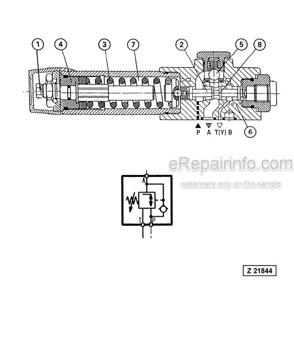
Travel Brake Valve
Pressure Reducing Valve
Directional Solenoid Valves
Hydraulic Cylinder
Auxiliary Pumps, Fan Drive
Auxiliary Gear Pumps
Swing Ring
-MAIN HYDRAULIC PUMPS AND PUMP REGULATION
Main Hydraulic Pump A7V / III) D
SL-Bearing
Function Of The Pump Governor
Pump Bearing Lubrication
Pump Governor Adjustments
Pump Regulation, General
Xi- Pressure Adjustment / Stop Gap Operation
Detailed Explanation Electronic Pump Regulation
Adjustments / Checks For The Electronic Pump Regulation
Testing The ESR Input And Output Voltage
Adjustments At The Ell – Module, Nominal Fine Tuning
Testing And Setting Of The Complete Regulation
Adjustments / Checks For The Electronic Regulation
EPM – Module, Function And Test
ESR – Modules, Function And Test
ELL – Module, Function And Test
Amplifier Module, Function And Test
Simplified Trouble Shooting Of The Electronic Regulation
-OPERATING HYDRAULIC
Hydraulic For The Attachment Cylinder
Adjustments For Attachment Cylinder Hydraulic
Swing Circuit, General
Swing Motor
Swing Gear And House Brake
Swing Brake Valve
Swing, Function
Checks And Adjustments
Travel Circuit, General
Rotary Distributor
Travel Motors
Travel Gear And House Brake
Travel Function
Adjustments / Checks
-HYDRAULIC TRACK TENSIONING SYSTEM
Function
Pressure Increasing Valve
Pressure Relief Valve; Pilot Operated
Adjustments / Pressure Checks
-HYDRAULIC OPERATED ACCESS LADDER
Access Ladder Hydraulic Operated
-CABLE DRUM
Central Refilling System
-HINTS FOR THE HYDRAULIC CIRCUIT DIAGRAM
Hints For Reading The Circuit Diagram
Legend Of The Hydraulic Circuit Diagram
Pressure Check Points
How To Read The Circuit Diagram
-HINTS FOR THE ELECTRIC CIRCUIT DIAGRAM
Markings Of Electrical Components In The Circuit Diagrams
Symbols
KMG Circuit Diagrams,
General Information
Explanation Of The Drawing Concept
Location Of The Main Terminal Boxes And Same Components
Heading A Circuit Diagram
Adjustments
Component List
-ELECTRONIC CONTROL SYSTEM – ECS
Introduction
Function
Layout Of Dash Board, (Part Of Operation Manual)
Text Monitoring System, (Part Of Operation Manual)
-LUBRICATION SYSTEM
Function
Adjustments
APPENDIX
What you get
You will receive PDF file with high-quality manual on your email immediately after the payment.


Reviews
There are no reviews yet.