


Factory Shop Manual For Komatsu Hydraulic Mining Shovel. Manual Contains Illustrations, Instructions, Diagrams For Step By Step Remove And Install, Assembly And Disassembly, Service, Inspection, Repair, Troubleshooting, Tune-Ups.
Format: PDF
Language: English
Pages: 441
Number: SMPC30006225 (december 2006)
Bookmarks: Yes
Wiring Diagrams: Yes
Hydraulic Diagrams: Yes
Model
Komatsu Hydraulic Mining Shovel
PC3000-1
SN 6225
Contents
INTRODUCTION
FOREWORD
TABLE OF CONTENTS
-MAIN ASSEMBLY GROUPS
General Layout
Drive
Control Blocks, Swing Gear
Undercarriage. Travel Drive
Driver’s Cab
-DRIVE
Prime Drive Assembly
Engine Mounts
Fan Drive And Cooler Assy
Coupling
Air Filter
Pump Distributor Gear
Spline Lubrication
Gear Lubrication
Location Of The Pumps, Drive Speeds And Flow Rates
-HYDRAULIC OIL TANK
Main Oil Tank
Return And Leak Oil Filter
Breather Filter
Location Of Pressure Switches And Sensors
-HYDRAULIC OIL COOLING
General
Hydraulic Oil Cooling Circuit
Adjustments
Fan Drive
Pressure Relief Valve And Solenoid Valve
Axial Piston Pump
Adjustments
Function Check For RPM-Control
-CONTROLLING
Pilot Pressure Supply
Checks And Adjustments Of Pilot Pressure
Checking The Accumulator Function
Travel Parking Brake
Function Check Of Travel Parking Brake
Swing Parking (House) Brake
-COMPONENTS
Distributor Manifold
Restrictor Block With Pressure Relief Valve
Anti Cavitation Valve Block
Proportional Solenoid Valve
Pressure Filter
Control Blocks
Travel Brake Valve
Pressure Reducing Valve
Directional Control Valve (“Solenoid Valve”)
Hydraulic Cylinder
Auxiliary Pumps (Fan Drive)
Auxiliary Gear Pumps
Swing Ring
-MAIN HYDRAULIC PUMPS
Main Hydraulic Pump A7V / HDD
Description Of The SL-Bearing
Function Of The Pump Governor
Pump Bearing Lubrication
Pump Governor Adjustments
Pump Regulation, General
Determination Of The Peak Point (Corner Value)
Hydraulic Regulation Adjustment, Stop Gap Operation
Detailed Explanation For The Electronic Regulation
Adjustments/Checks For The Electronic Regulation
Adjusting The Rpm Sensor (MPU)
Adjustments / Checks For The Ell – Module, Nominal Fine Tuning
Testing And Setting For The Complete Regulation
Checks / Function Test / Fault Finding At Job Site
EPM – Module, Function And Test
ERM – Module, Function And Test
ELL – Module, Function And Test
Testing The Proportional Amplifier Module, A36
Simplified Trouble Shooting Of The Electronic Control
-OPERATING HYDRAULIC
Hydraulic For Attachment Cylinder
Adjustments For Attachment Cylinder Hydraulic
Swing Circuit, General
Swing Motor
Swing Gear And Swing Parking Brake
Swing Brake Valve
Swing, Function
Checks And Adjustments
Travel Circuit
Rotary Distributor
Travel Motor (Axial Piston Motor A2Fm)
Travel Gear And Parking Brake
Travel, Function
Adjustments/Checks
-HYDRAULIC TRACK TENSION SYSTEM
Hydraulic Track Tension System
Function: Z 22281
Pressure Increasing Valve Type: MO 7010
Pressure Relief Valve, Direct Operated Type: DBD S
Adjustments / Pressure Checks
-ACCESS LADDER HYDRAULIC OPERATED
Access Ladder Hydraulic Operated
-CENTRAL REFILLING SYSTEM
Central Refilling System
-HINTS FOR THE HYDRAULIC CIRCUIT DIAGRAM
Hints For Reading The Circuit Diagram
Legend To The Hydraulic Circuit Diagram PC 3000, With Diesel Engine
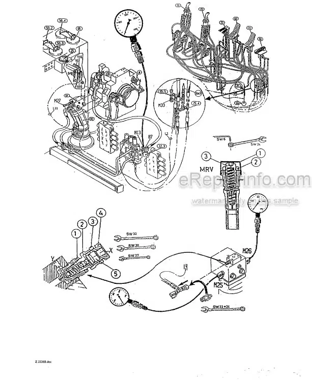
Pressure Check Points
How To Read The Circuit Diagram
-HINTS FOR THE ELECTRIC CIRCUIT DIAGRAM
Markings Of Electrical Components In The Circuit Diagrams
Symbols
KMG Circuit Diagrams
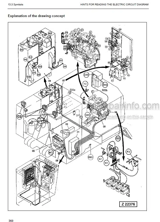
Explanation Of The Drawing Concept
Location Of The Main Terminal Boxes And Some Important Components
Reading A Circuit Diagram
Adjustments
Component List
-ELECTRONIC TEXT MONITORING SYSTEM
Introduction
Function
Layout Of Dash Board
Text Monitoring System
EFD – Module, Function And Trouble Shooting
HYDRAULIC PLAN
ELECTRICAL PLAN
What you get
You will receive PDF file with high-quality manual on your email immediately after the payment.


Reviews
There are no reviews yet