


Factory Service Manual For Komatsu Hydraulic Excavator. Manual Contains Illustrations, Instructions, Diagrams For Step By Step Remove And Install, Assembly And Disassembly, Service, Inspection, Repair, Troubleshooting, Tune-Ups.
Format: PDF
Language: English
Pages: 800
Issued: november 2006
Bookmarks: Yes
Searchable: Yes
Model
Komatsu Hydraulic Excavator
PC4000
SN 08175; 08178; 08179; 08183; 08184
Contents
SAFETY – FOREWORD
TECHNICAL DATA (LEAFLET)
ASSEMBLY PROCEDURE (BROCHURE)
-MAIN ASSEMBLY GROUPS
General Lay Out
-DRIVE
Prime drive assembly
-HYDRAULIC OIL TANK
General Lay Out
-HYDRAULIC OIL COOLING
General
Function Of The Hydraulic Oil Cooling Circuit
Adjustment Of The Back Pressure Valve
Fan Drive (Two Stage Cooler Fan Rpm Control)
Pressure Relief Valves And Solenoid Valve
Fixed Displacement Pump, With Variable Setting
Adjustment Of The Cooler Fan Drive Speed
Function Check Of Fan Speed Control
-CONTROLLING
Control And Filter Panel Location Of Components (Valves, Switches, Sensors Etc.
Pilot Pressure Supply And Adjustments
Remote Control Valves Arrangement
Function Principle Of The Electro-Hydraulic- Proportional Control
Potentiometer Control (Lever, Joy Stick)
Potentiometer Control (Pedal)
Proportional Amplifier Module, Type A (For Swing Brake Only)
Proportional Amplifier Module, Type B (For Boom, Stick, Bucket, Swing And Travel)
Ramp Tune Module (Analogue Command Value Module For Boom, Stick, Travel And Swing Function)
Adjustments Of Amplifier Modules (General)
Adjusting The Amplifiers Type B
Adjusting The Amplifiers Type A
Adjusting The Ramp Tune Module
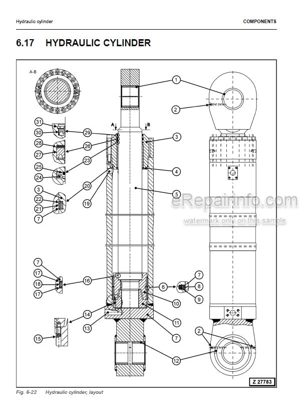
-COMPONENTS
Hydraulic
Mechanical
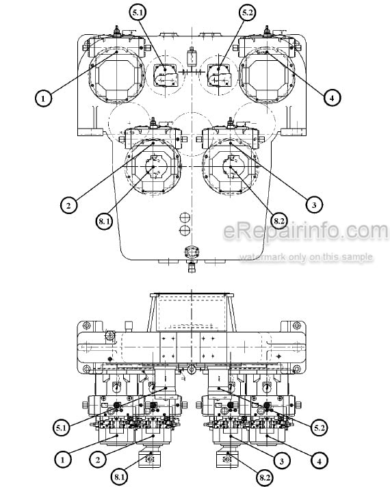
-MAIN HYDRAULIC PUMPS AND PUMP REGULATION
Main Pumps
Electronic Pump Regulation System
Hydraulic Constant Regulation System
Determination Of The Peak Point
Engine Speed Sensor (Pick Up)
Energy Efficiency
-OPERATING HYDRAULIC
Hydraulic For The Attachment Cylinder FSA And BHA
Hydraulic For The Swing Circuit
Hydraulic For The Travel Circuit
-HYDRAULIC TRACK TENSIONING SYSTEM
Functional Description
Pressure Increasing Valve
Tensioning Cylinder
Adjustments Checks
Functional Test
-HYDRAULIC OPERATED EXCESS LADDER
General
Function Of Hydraulically Operated Access Ladder
Adjustments / Checks
-CENTRAL REFILLING SYSTEM (HYDRAULIC OPERATED REFILLING ARM)
General
Function
-HINTS FOR THE HYDRAULIC CIRCUIT DIAGRAM
General
Symbols
Legend For The Circuit Diagram
-HINTS FOR THE ELECTRIC CIRCUIT DIAGRAM
Designation Of Electrical Devices
Symbols
General Information
Reading A Circuit Diagram
Component List
-VEHICLE HEALTH MONITORING SYSTEM (VHMS)
Health Monitor (MH 801) for PC4000
Colored Graphic Console (CGC)for PC4000
-LUBRICATION SYSTEMS
Symbols
Safety Instructions
Abbreviations
Introduction
Component Explanation
Operating and Controlling
Adjustments
Trouble Shooting
Commissioning
What you get
You will receive PDF file with high-quality manual on your email immediately after the payment.


Reviews
There are no reviews yet.