


Factory Shop Manual For Komatsu Hydraulic Mining Shovel. Manual Contains Illustrations, Instructions, Diagrams For Step By Step Remove And Install, Assembly And Disassembly, Service, Inspection, Repair, Troubleshooting, Tune-Ups.
Format: PDF
Language: English
Pages: 517
Number: SMPC550015011 (august 2006)
Bookmarks: Yes
Wiring Diagrams: Yes
Hydraulic Diagrams: Yes
Model
Komatsu Hydraulic Mining Shovel
PC5500-6
SN 15011
Contents
INTRODUCTION
TABLE OF CONTENTS
FOREWORD
-MAIN ASSEMBLY GROUPS
General Lay Out
Drive
Control Blocks
Undercarriage. Travel Drive
Driver’s Cab
-DRIVE
Prime Drive Assembly
Engine Mounts: Cummins Engine
Coupling
Air Filter
Fan Drive And Radiator Assy
Pump Distributor Gear
Hydraulic Pumps Locations, Their Drive Speeds And Flow Rates
-HYDRAULIC OIL TANK
Main Hydraulic Tank
Return And Leak Oil Filter
Breather Filter
-HYDRAULIC OIL COOLING
General
Hydraulic Oil Cooling Circuit
Adjustments
Fan Drive
Axial Piston Pump
Adjustments
-CONTROLLING
Lay Out
Control Panel
Pilot Pressure Supply And Adjustments
Remote Control Valves Arrangement
Function Principle Of The Electro-Hydraulic Proportional Control
Proportional Amplifier Modules
Ramp Time Modules
Adjustments Of Amplifier And Ramp Time Modules
Adjustment And Checks For The Pressure Reducing Valves For The Pump Regulation
-COMPONENTS
Main Control Blocks And High Pressure Filter
Distributor Manifold
Restrictor Blocks
Anti Cavitation Valve Block
Remote Control Valves
Directional Solenoid Valves
Proportional Solenoid Valves
Pressure Relief Valve, Pilot Operated
High Pressure Filter
Control Blocks
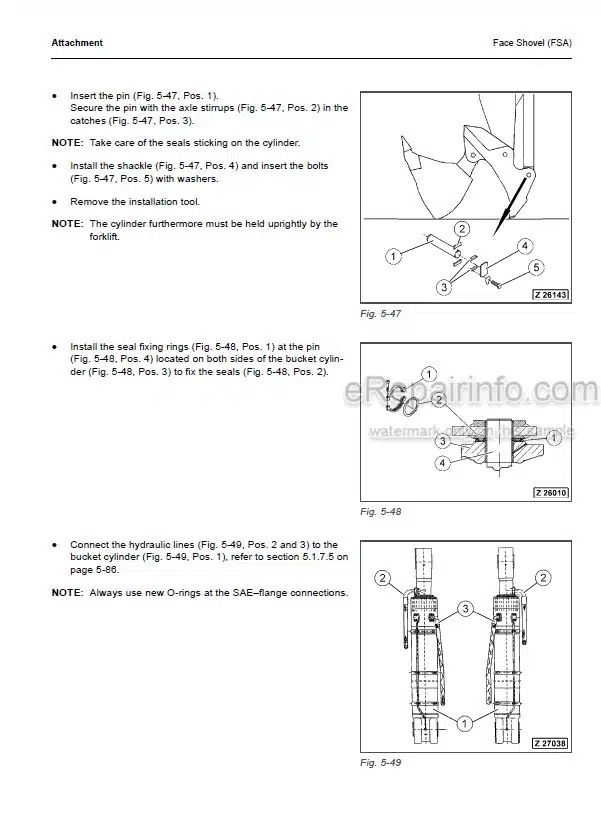
Hydraulic Cylinder
-MAIN HYDRAULIC PUMPS
Hydraulic Pumps Locations
Function Explanation
Checks And Adjustments
Pump Regulation System Lay Out
-OPERATING HYDRAULIC
Hydraulic For The Attachment Cylinder
Electric/Hydraulic Flowcharts. LBA
Adjustments For Attachment Cylinders
Swing Circuit
Travel Circuit
-HYDRAULIC TRACK TENSION SYSTEM
Hydraulic Track Tension System
Function
Pressure Increasing Valve
Tensioning Cylinder
Pressure Checks/Adjustments
-HYDRAULIC OPERATED ACCESS LADDER
Function
-CENTRAL REFILLING SYSTEM
Function
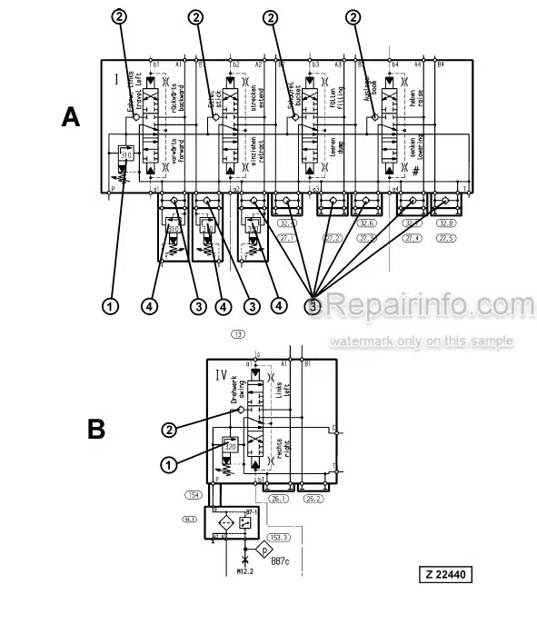
-HINTS FOR THE HYDRAULIC CIRCUIT DIAGRAM
Hints For Reading The Circuit Diagram
Legend For The Circuit Diagram
-HINTS FOR THE ELECTRIC CIRCUIT DIAGRAM
Markings Of Electrical-Symbols
General Information
Explanation Of The Drawing Concept
Terminal Plans Sheets
How To Read The Circuit Diagram
-HYDRAULICALLY DRIVEN LUBE PUMP POWER MASTER III
Function
Adjustments
-ONE LINE SYSTEM WITH HYDRAULICALLY DRIVEN “POWER MASTER III” PUMP
Function
Electric Circuit Diagram Explanation
Sonar Sensor For Grease Level
Adjustments
-PINION TYPE SYSTEM WITH HYDR. DRIVEN “POWER MASTER III” PUMP
Function
Electric Circuit Diagram Explanation
Adjustments
-COMPONENTS
Hydraulically Driven Lube Pump
Injectors
End-Of-Line Switch
HYDRAULIC PLANS
ELECTRICAL PLANS
FLOWCHART
What you get
You will receive PDF file with high-quality manual on your email immediately after the payment.


Reviews
There are no reviews yet.