


Factory Shop Manual For Komatsu Wheel Excavator. Manual Contains Illustrations, Instructions, Diagrams For Step By Step Remove And Install, Assembly And Disassembly, Service, Inspection, Repair, Troubleshooting, Tune-Ups.
Format: PDF
Language: English
Pages: 435
Number: UEBM002800 (may 2007)
Bookmarks: Yes
Searchable: Yes
Wiring Diagrams: Yes
Hydraulic Diagrams: Yes
Model
Komatsu Wheel Excavator
PW130-7K
SN K40001 And Up
Contents
FOREWORD
-GENERAL
Specification Dimension Drawings
Working Range
Specifications
Weight Table
Fuel, Coolant, And Lubricants
-STRUCTURE, FUNCTION AND MAINTENANCE STANDARD
Engine Related Parts
PTO (Coupling)
Radiator – Oil Cooler – Charge Air Cooler
Power Train
Swing Circle
Swing Machinery & Motor
Undercarriage
Transmission
Travel Motor
Clutch Control Circuit
Axle
Suspension Lock Cylinder
Braking System
Brake/Steer Pump
Priority Valve
Power Brake Valve
Accumulator For Brake System
Steering Train
Steering Column
Orbitrol Valve
Hydraulic Layout Drawing
Hydraulic Circuit Diagram
Hydraulic Tank
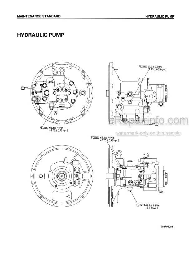
Hydraulic Pump
Pilot Pressure Control System
Control Valve
CLSS
Swing Motor
Centre Swivel Joint
Travel PPC Pedal
Work Equipment – Swing PPC Valve
Service PPC Valve
Solenoid Valve Manifold
Boom Safety Valve
Hydraulic Cylinder (Boom-Arm-Bucket)
Outrigger Cylinder
Dozer Cylinder
Work Equipment
Air Conditioner
Electrical Wiring Diagram
Engine Control System
Electronic Control System
Machine Monitor System
Overload Warning Device
Sensor
Breaker Mode Hydraulic Performance (Main Valve Bypassed)
Breaker Mode Hydraulic Performance (Via Main Valve)
Travel System
Steering System
Service Brake And Suspension System
-TESTING AND ADJUSTING
Inspection And Adjustment Of Air Compressor Belt Tension
Adjustment Of Engine Speed Sensor
Testing And Adjusting Governor Motor Lever Stroke
Measurement Of Clearance In Swing Circle Bearings
Testing And Adjusting Hydraulic Pressure In Work Equipment, Swing And Travel Circuit
Testing And Adjusting PC Valve Output Pressure (Servo Piston Input Pressure)
Testing And Adjusting LS Valve Output Pressure (Servo Piston Input Pressure) And LS Differential Pressure
Inspection And Adjustment Of Control Circuit Oil Pressure
Measurement Of Solenoid Valve Output Pressure
Testing Travel Motor Relief Pressure
Adjusting Travel Motor Relief Pressure
Testing Locations Causing Hydraulic Drift Of Work Equipment
Measuring Oil Leakage
Release Of Remaining Pressure In Hydraulic Circuit
Bleeding Air
Inspection Procedures For Diode
Measuring Rotating Speed Of Propshaft
Testing Transmission Clutch Control Circuit
Special Function Of Monitor Panel
Preparations For Troubleshooting Electrical System
-OTHERS
Hydraulic Circuit Diagram
Electrical Circuit Diagram
What you get
You will receive PDF file with high-quality manual on your email immediately after the payment.


Reviews
There are no reviews yet.