


Factory Shop Manual For Komatsu Wheel Excavator. Manual Contains Illustrations, Instructions, Diagrams For Step By Step Remove And Install, Assembly And Disassembly, Service, Inspection, Repair, Troubleshooting, Tune-Ups.
Format: PDF
Language: English
Pages: 956
Number: VEBM390100 (issued 2006)
Bookmarks: Yes
Searchable: Yes
Wiring Diagrams: Yes
Hydraulic Diagrams: Yes
Model
Komatsu Wheel Excavator
PW160-7H
SN H50051 And Up
Contents
FOREWORD
-GENERAL
Specification Dimension Drawings
Working Range
Specifications
Weight Table
Fuel, Coolant, And Lubricants
-STRUCTURE, FUNCTION AND MAINTENANCE STANDARD
Engine Related Parts
Radiator – Oil Cooler – Charge Air Cooler
Power Train
Swing Circle
Swing Machinery
Swing Motor
Undercarriage
Transmission
Travel Motor
Clutch Control Circuit
Axle
Suspension Lock Cylinder
Braking System
Brake/Steer Pump
Priority Valve
Power Brake Valve
Accumulator For Brake System
Steering Train
Steering Column
Orbitrol Valve
Hydraulic Layout Drawing
Hydraulic Circuit Diagram
Hydraulic Tank
Hydraulic Pump
Pilot Pressure Control System
Control Valve
CLSS
Centre Swivel Joint
Travel PPC Pedal
Work Equipment • Swing PPC Valve
Service PPC Pedal
Solenoid Valve Manifold
Boom Safety Valve
Hydraulic Cylinder (Boom-Arm-Bucket)
Outrigger Cylinder
Dozer Cylinder
Work Equipment
Air Conditioner
Electrical Wiring Diagram
Engine Control System
Electronic control System
Machine Monitor System
Overload Warning Device
Sensor
1st Attachment Circuit Hydraulic Performance (Main Valve Bypassed)
Travel System
Steering System
Service Brake and Suspension System
-TESTING AND ADJUSTING
Standard Value Table For Engine Related Parts
Standard Value Table For Chassis Related Parts
Testing And Adjusting
Troubleshooting
-DISASSEMBLY AND ASSEMBLY
Special Tools
Precautions When Performing Operation
Governor Motor Assembly
Starting Motor Assembly
Fuel Injection Pump Assembly
Engine Front Seal
Engine Rear Seal
Cylinder Head Assembly
Combination Cooler Assembly
Engine And Hydraulic Pump Assemblies
Travel Motor Assembly
Disassembly And Assembly Of Travel Motor
Swing Motor And Swing Machinery Assembly
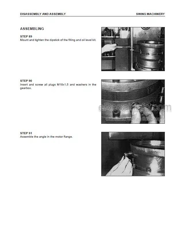
Swing Machinery Disassembly And Assembly
Swing Motor Disassembly And Assembly
Front Axle Assembly
Disassembly And Assembly
Rear Axle And Transmission Assembly
Disassembly And Assembly Of Rear Axle
Disassembly And Assembly Transmission
Propshaft Assembly
Wheels
Suspension Lock Cylinder Assembly
Outrigger Assembly
Dozer Blade Assembly
Swing Circle Assembly
Revolving Frame Assembly
Center Swivel Joint Assembly
Disassembly And Assembly
Hydraulic Tank Assembly
Fuel Tank Assembly
Control Valve Assembly
LS Select Valve Assembly
Pressure Compensation Valve Assembly
Main Relief Valve Assembly
LS Control EPC Valve Assembly
EPC Solenoid Valve Assembly
PPC Valve Block Assembly
Manifold Block Assembly
Oil Seal In Hydraulic Pump
Input Shaft
Work Equipment PPC Valve
Assembly
Disassembly And Assembly
Hydraulic Cylinder Assembly
2 Piece Boom Assembly
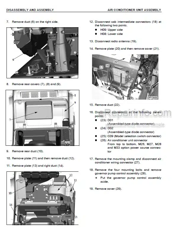
Air Conditioner Unit
Counterweight Assembly
Operator’s Cab Assembly
Monitor Assembly
Governor Pump Controller Assembly
-OTHERS
Hydraulic Circuit Diagram
Electrical Circuit Diagram
What you get
You will receive PDF file with high-quality manual on your email immediately after the payment.


Reviews
There are no reviews yet